CY3263-COLORLOCK Cypress Semiconductor Corp, CY3263-COLORLOCK Datasheet - Page 13
CY3263-COLORLOCK
Manufacturer Part Number
CY3263-COLORLOCK
Description
KIT EVAL COLOR-LOCK
Manufacturer
Cypress Semiconductor Corp
Series
EZ-Color™r
Datasheet
1.CY3263-COLORLOCK.pdf
(64 pages)
Specifications of CY3263-COLORLOCK
Main Purpose
Lighting, RGB LED Controller
Embedded
Yes, MCU, 8-Bit
Utilized Ic / Part
CY8CLEDxx
Primary Attributes
EZ-Color™ LED Driver MCUs Generate Colors using Optical Feedback
Secondary Attributes
View 1931 CIE Coordinates via LCD, Red, Green, and Blue 1W LEDs
Core Chip
CY3263
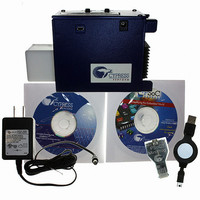
Kit Contents
CY3263-ColorLock Evaluation Board, Tools CD, USB Cable, Power Supply Adapter
Lead Free Status / RoHS Status
Lead free / RoHS Compliant
Other names
428-2271


2.1
CY3263-ColorLock EZ-Color Evaluation Kit Guide, Doc. # 001-44081 Rev. *A
2.
ColorLock Monitor
Note The ColorLock Monitor application is for demonstration purposes only and is completely sepa-
rate from the Tuner in PSoC Express, which is a design tool, and will not function while PSoC
Express is open.
The CY3263-ColorLock EZ-Color Evaluation Kit board demonstrates the ability of a EZ-Color con-
troller to provide closed-loop, high accuracy control for three primary, high brightness LEDs to create
mixed-color output. To provide the closed-loop capability, a TAOS TSC-230 color sensor is used to
determine the current color being produced by the LEDs. This information is fed to the EZ-Color
LED16 controller to determine the correct brightness for each of three primary, high brightness
LEDs. The three LEDs are the colors red, green, and blue. The application described in this chapter
controls the ColorLock evaluation board through a USB port on a personal computer that is using the
Windows Vista or Windows XP operating system.
Representing Colors
The application can represent either of two standard color coordinate systems: CIE 1931 x, y or CIE
1976 u’, v’. These two modes are available under the Settings > Color Space pull-down on the appli-
cation tool-bar. The CIE 1931 coordinate system is automatically selected when the application is
started. The CIE Color Mix Mode displays the 1931 CIE Color chart. This chart represents the range
of colors visible to the human eye. The interior portion of the triangle displayed on the color chart
represents the range of colors that can be represented by the LEDs on the ColorLock board. All syn-
thetic light sources, such as LEDs or incandescent lights, produce some limited range of the spec-
trum of colors the human eye can see. The triangle shows the colors that can be displayed by mixing
the light from the three LEDs on the evaluation board. Clicking anywhere within the triangle will place
a dot at the selected point. The corresponding CIE coordinates for that color are transmitted to the
ColorLock board, where the selected color is displayed by adjusting the three LEDs to brightness
levels that create the mixed color. The resulting coordinates are shown numerically in the Color
panel displayed below the color chart. If the CIE 1931 chart is selected, the x, y coordinates are
shown. If the CIE 1976 chart is selected, the u’, v’ coordinates are displayed.
The Manual Control Mode is an alternative to specifying colors using CIE coordinates. This mode
displays three slider controls, one for each LED on the board. Moving a slider from left-to-right
causes the corresponding LED to light from zero to one-hundred percent of this maximum bright-
ness. To control the LEDs manually, check Disable Feedback below the three horizontal slider con-
trols displayed on the bottom right portion of the application display. Notice that all controls related to
WARNING: HIGH BRIGHTNESS LEDs CAN CAUSE PERMANENT
EYE DAMAGE!
Do not look at the LEDs if they are not covered by the protective
enclosure. The LEDs illuminate at a very high intensity and can
cause permanent eye damage if they are viewed without the
protective enclosure.
13
Related parts for CY3263-COLORLOCK
Image
Part Number
Description
Manufacturer
Datasheet
Request
R

Part Number:
Description:
Manufacturer:
Cypress Semiconductor Corp
Datasheet:
Part Number:
Description:
Manufacturer:
Cypress Semiconductor Corp
Datasheet:
Part Number:
Description:
Manufacturer:
Cypress Semiconductor Corp
Datasheet:
Part Number:
Description:
Manufacturer:
Cypress Semiconductor Corp
Datasheet:
Part Number:
Description:
Manufacturer:
Cypress Semiconductor Corp
Datasheet: