CY3263-COLORLOCK Cypress Semiconductor Corp, CY3263-COLORLOCK Datasheet - Page 7
CY3263-COLORLOCK
Manufacturer Part Number
CY3263-COLORLOCK
Description
KIT EVAL COLOR-LOCK
Manufacturer
Cypress Semiconductor Corp
Series
EZ-Color™r
Datasheet
1.CY3263-COLORLOCK.pdf
(64 pages)
Specifications of CY3263-COLORLOCK
Main Purpose
Lighting, RGB LED Controller
Embedded
Yes, MCU, 8-Bit
Utilized Ic / Part
CY8CLEDxx
Primary Attributes
EZ-Color™ LED Driver MCUs Generate Colors using Optical Feedback
Secondary Attributes
View 1931 CIE Coordinates via LCD, Red, Green, and Blue 1W LEDs
Core Chip
CY3263
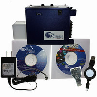
Kit Contents
CY3263-ColorLock Evaluation Board, Tools CD, USB Cable, Power Supply Adapter
Lead Free Status / RoHS Status
Lead free / RoHS Compliant
Other names
428-2271


1.3
1.3.1
1.3.2
1.3.3
CY3263-ColorLock EZ-Color Evaluation Kit Guide, Doc. # 001-44081 Rev. *A
Board Layout
The On/Off Button
The CY3263-ColorLock EZ-Color evaluation hardware has two buttons and a liquid crystal display.
These allow the board to be demonstrated without using a personal computer to control the board.
When held properly for use, the buttons liquid crystal display face upward. When held in this orienta-
tion, the right-most button alternately turns the high brightness LEDs on and off. The default setting
when power is applied is off; pressing this right-most button will illuminate the LEDs.
The Color Selection Button
The left-most button along the bottom edge cycles between seven preset colors. The initial color is
white (all three LEDs are illuminated at high intensity). Pressing this button changes to the next color
of the seven preset colors. The color sequence cycles through white, red, green, blue, yellow,
magenta and cyan.
Note If the board has been controlled from a personal computer using the USB interface, the color
displayed upon powering the board and pressing the On/Off button will be the last color setting
selected when using the monitor application. If the board has never been controlled from a personal
computer, or the last color selected could not be displayed at the selected intensity, the LEDs will not
illuminate (an impossible color and intensity combination has been selected). Pressing the color
selection button will select a valid color for display from the seven preset colors and the LEDs will
illuminate with that color.
The Liquid Crystal Display
The liquid crystal display displays the currently selected color using CIE 1931 color coordinates. The
values displayed on the top line of the LCD represent the CIE x, y coordinates for the currently
selected color, whether chosen from the seven preset colors or selected from the ColorLock Monitor
application (if using the factory firmware). The two values on the bottom line of the display represent
the CIE x, y coordinate currently being sensed by the integrated color sensor. The difference
between these two values represents the error. The coordinates for the currently sensed color are
displayed in real-time and are continuously varying as the EZ-Color continually senses and corrects
for the error in the displayed color.
If the LEDs are illuminated, an asterisk (‘*’) is displayed on the left end of the top row of the liquid
crystal display (this is useful if the last color selected cannot be displayed with the given LEDs,
resulting in the LEDs being turned off).
Figure 1-1. ColorLock Board
Introduction
7
Related parts for CY3263-COLORLOCK
Image
Part Number
Description
Manufacturer
Datasheet
Request
R

Part Number:
Description:
Manufacturer:
Cypress Semiconductor Corp
Datasheet:
Part Number:
Description:
Manufacturer:
Cypress Semiconductor Corp
Datasheet:
Part Number:
Description:
Manufacturer:
Cypress Semiconductor Corp
Datasheet:
Part Number:
Description:
Manufacturer:
Cypress Semiconductor Corp
Datasheet:
Part Number:
Description:
Manufacturer:
Cypress Semiconductor Corp
Datasheet: