CY3263-COLORLOCK Cypress Semiconductor Corp, CY3263-COLORLOCK Datasheet - Page 20
CY3263-COLORLOCK
Manufacturer Part Number
CY3263-COLORLOCK
Description
KIT EVAL COLOR-LOCK
Manufacturer
Cypress Semiconductor Corp
Series
EZ-Color™r
Datasheet
1.CY3263-COLORLOCK.pdf
(64 pages)
Specifications of CY3263-COLORLOCK
Main Purpose
Lighting, RGB LED Controller
Embedded
Yes, MCU, 8-Bit
Utilized Ic / Part
CY8CLEDxx
Primary Attributes
EZ-Color™ LED Driver MCUs Generate Colors using Optical Feedback
Secondary Attributes
View 1931 CIE Coordinates via LCD, Red, Green, and Blue 1W LEDs
Core Chip
CY3263
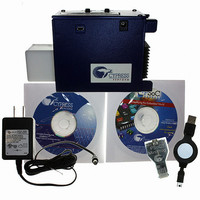
Kit Contents
CY3263-ColorLock Evaluation Board, Tools CD, USB Cable, Power Supply Adapter
Lead Free Status / RoHS Status
Lead free / RoHS Compliant
Other names
428-2271


ColorLock Monitor
2.3.2
20
Toolbar Icons and Menubar Options
The ColorLock monitor application can be controlled using the toolbar icons or by using menu bar
options. Both provide the complete set of control options available in the monitor. This section
describes each icon and the corresponding menu-bar selection. In the descriptions that follow, each
icon is shown, followed by the corresponding menu selection path on the menu bar, followed by a
description of the use and function of the control.
version and copyright information. Clicking the OK button closes the About window.
(Monitor → Run) When selected, this icon starts the monitor. The charts begin displaying real-
time information about the current state of the ColorLock unit. Once selected, the Run control is
rendered inactive and is “grayed out,” as the monitor is now running.
(Monitor → Stop) This control stops the monitor. All charting stops, but the graphical information
recorded in the charts is preserved. Once selected, the Stop control is rendered inactive and is
“grayed out,” as the monitor is now stopped.
(Settings → ColorSpace → CIE1931) This icon causes the monitor to use CIE 1931 color coor-
dinates. This is the default coordinate system when the monitor is started. When selected, the
CIE 1931 color chart is displayed in the lower left pane and the charts display data using the x, y
coordinate values used in the CIE 1931 coordinate system.
(Settings → ColorSpace → CIE1976) This icon causes the monitor to use CIE 1976 color coor-
dinates. When selected, the CIE 1976 color chart is displayed in the lower left pane and the
charts display data using the u’, v’ coordinate values used in the CIE 1976 coordinate system.
(Settings → LED Color Coordinates) This icon results in a pop-up menu that shows the current
CIE 1931 x, y coordinates for the LEDs being used in the ColorLock unit. These values repre-
sent the primary colors that define the color gamut being displayed by the ColorLock unit. The
values in this window are measured from the existing LEDs on the board. New values can be
entered, which will only change the color gamut in the window, it does not change the capability
of the LEDs to create different colors. In general there is no reason to change these settings
unless the LED board in the ColorLock unit is being changed. If the system is calibrated using
the calibration tool, these values will be overwritten with the new gamut information.
(Tools → Calibration) This control results in a pop-up menu that allows for the calibration of the
ColorLock unit’s optical feedback system. Each of the sensor’s three color channels must be
calibrated with values obtained from an external color meter. The first menu displayed calibrates
the red color channel of the sensor, the second menu the green channel, and the third menu the
blue sensor. Each menu requires three color values from the color meter, corresponding to the
red, green and blue components for the given channel. Upon completion, the monitor sends the
calibration information to the ColorLock unit, where it is stored. The calibration information is
stored in non-volatile flash, unless the contents of flash memory is overwritten.
(Tools → Show Calibration Matrices) This control results in a pop-up window that displays the
values of the current calibration matrices. The values shown cannot be changed using this win-
dow, only the calibration menu can change the values of the three matrices displayed. The Col-
orLock firmware uses the contents of these matrices to transform the current sensor readings
into PrISM values for each of the three LEDs. For more calibration information for this system,
refer to Application Note
(Help → About) This menubar selection results in a pop-up window that displays the application
44533 ColorLock Optical Feedback for
CY3263-ColorLock EZ-Color Evaluation Kit Guide, Doc. # 001-44081 Rev. *A
EZ-Color.
Related parts for CY3263-COLORLOCK
Image
Part Number
Description
Manufacturer
Datasheet
Request
R

Part Number:
Description:
Manufacturer:
Cypress Semiconductor Corp
Datasheet:
Part Number:
Description:
Manufacturer:
Cypress Semiconductor Corp
Datasheet:
Part Number:
Description:
Manufacturer:
Cypress Semiconductor Corp
Datasheet:
Part Number:
Description:
Manufacturer:
Cypress Semiconductor Corp
Datasheet:
Part Number:
Description:
Manufacturer:
Cypress Semiconductor Corp
Datasheet: