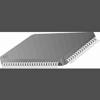
CR16MCS9VJE8 National Semiconductor, CR16MCS9VJE8 Datasheet - Page 73

CR16MCS9VJE8
Manufacturer Part Number
CR16MCS9VJE8
Description
16-Bit Microcontroller IC
Manufacturer
National Semiconductor
Datasheet
1.CR16MCS9VJE8.pdf
(156 pages)
Specifications of CR16MCS9VJE8
Controller Family/series
CR16X
Core Size
16 Bit
Program Memory Size
64K X 8 Flash
Digital Ic Case Style
PQFP
No. Of Pins
80
Mounting Type
Surface Mount
Clock Frequency
25MHz
Lead Free Status / RoHS Status
Contains lead / RoHS non-compliant
Available stocks
Company
Part Number
Manufacturer
Quantity
Price
Company:
Part Number:
CR16MCS9VJE8
Manufacturer:
ON
Quantity:
8 917
Company:
Part Number:
CR16MCS9VJE8-CBB
Manufacturer:
ON
Quantity:
846
Company:
Part Number:
CR16MCS9VJE8-CBC
Manufacturer:
ON
Quantity:
109
Company:
Part Number:
CR16MCS9VJE8-CBD
Manufacturer:
ON
Quantity:
17
Company:
Part Number:
CR16MCS9VJE8-CBE
Manufacturer:
ON
Quantity:
1 950
While the TSFT is shifting out the current character on the
TDXn pin, the UnTBUF register may be loaded by the soft-
ware with the next byte to be transmitted. When the TSFT fin-
ishes transmission of the last stop bit within the current
frame, the contents of UnTBUF are transferred to the TSFT
register and the Transmit Buffer Empty flag (UnTBE) is set.
The UnTBE flag is automatically reset by the USART when
the software loads a new character into the UnTBUF register.
During transmission, the UnXMIP bit is set high by the
USART. This bit is reset only after the USART has sent the
last frame bit of the current character and the UnTBUF reg-
ister is empty.
The receive shift register (RSFT) and the receive buffer
(UnRBUF) double-buffer the data being received. Serial data
received on the RDXn pin is shifted into the RSFT register at
the first falling edge of the clock. Each subsequent falling
edge of the clock causes an additional bit to be shifted into
the RSFT register. The USART assumes a complete charac-
ter has been received after the correct number of rising edg-
es on CKXn (based on the selected frame format) have been
detected. Upon receiving a complete character, the contents
of the RSFT register are copied into the UnRBUF register
and the Receive Buffer Full flag (UnRBF) is set. The UnRBF
flag is automatically reset when the software reads the char-
acter from the UnRBUF register.
The transmitter and receiver may be clocked from either an
external source provided to the CKXn pin or by the internal
baud rate generator. In the latter case, the clock signal is
placed on the CKXn pin as an output.
18.2.3
The Attention mode is available for networking this device
with other processors. This mode requires the 9-bit data for-
mat with no parity. The number of start bits and number of
stop bits are programmable. In this mode, two types of 9-bit
characters are sent on the network: address characters con-
sisting of 8 address bits and a 1 in the ninth bit position and
data characters consisting of 8 data bits and a 0 in the ninth
bit position.
While in Attention mode, the USART receiver monitors the
communication flow but ignores all characters until an ad-
dress character is received. Upon the receipt of an address
character, the contents of the receive shift register are copied
RDX
Figure 34. USART Synchronous Communication
CKX
TDX
Attention Mode
Sample Input
73
to the receive buffer. The UnRBF flag is set and an interrupt
(if enabled) is generated. The UnATN bit is automatically re-
set to zero, and the USART begins receiving all subsequent
characters. The software must examine the contents of the
UnRBUF register and respond by accepting the subsequent
characters (by leaving the UnATN bit reset) or waiting for the
next address character (by setting the UnATN bit again).
The operation of the USART transmitter is not affected by the
selection of this mode. The value of the ninth bit to be trans-
mitted is programmed by setting or clearing a bit called
UnXB9 in the USART Frame Select register. The value of the
ninth bit received is read from UnRB9 in the USART Status
Register.
18.2.4
The Diagnostic mode is available for testing of the USART. In
this mode, the TDXn and RDXn pins are internally connected
together, and data that is shifted out of the transmit shift reg-
ister is immediately transferred to the receive shift register.
This mode supports only the 9-bit data format with no parity.
The number of start and stop bits is programmable.
18.2.5
The format shown in Figure35 consists of a start bit, seven
data bits (excluding parity), and one or two stop bits. If parity
bit generation is enabled by setting the UnPEN bit, a parity
bit is generated and transmitted following the seven data bits.
The format shown in Figure36 consists of one start bit, eight
data bits (excluding parity), and one or two stop bits. If parity
bit generation is enabled by setting the UnPEN bit, a parity
bit is generated and transmitted following the eight data bits.
The format shown in Figure37 consists of one start bit, nine
data bits, and one or two stop bits. This format also supports
the USART attention feature. When operating in this format,
all eight bits of UnTBUF and UnRBUF are used for data. The
2a
2b
2c
1a
1b
1c
1
2
Figure 35. Seven Data Bit Frame Options
Figure 36. Eight Data Bit Frame Options
START
START
START
START
START
START
BIT
BIT
BIT
BIT
Diagnostic Mode
Frame Format Selection
START
START
BIT
BIT
BIT
BIT
7 BIT DATA
7 BIT DATA
7 BIT DATA
7 BIT DATA
8 BIT DATA
8 BIT DATA
8 BIT DATA
8 BIT DATA
S
PA
PA
PA
PA
www.national.com
S
2S
2S
S
S
2S
2S


