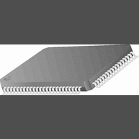
CR16MCS9VJE8 National Semiconductor, CR16MCS9VJE8 Datasheet - Page 83

CR16MCS9VJE8
Manufacturer Part Number
CR16MCS9VJE8
Description
16-Bit Microcontroller IC
Manufacturer
National Semiconductor
Datasheet
1.CR16MCS9VJE8.pdf
(156 pages)
Specifications of CR16MCS9VJE8
Controller Family/series
CR16X
Core Size
16 Bit
Program Memory Size
64K X 8 Flash
Digital Ic Case Style
PQFP
No. Of Pins
80
Mounting Type
Surface Mount
Clock Frequency
25MHz
Lead Free Status / RoHS Status
Contains lead / RoHS non-compliant
Available stocks
Company
Part Number
Manufacturer
Quantity
Price
Company:
Part Number:
CR16MCS9VJE8
Manufacturer:
ON
Quantity:
8 917
Company:
Part Number:
CR16MCS9VJE8-CBB
Manufacturer:
ON
Quantity:
846
Company:
Part Number:
CR16MCS9VJE8-CBC
Manufacturer:
ON
Quantity:
109
Company:
Part Number:
CR16MCS9VJE8-CBD
Manufacturer:
ON
Quantity:
17
Company:
Part Number:
CR16MCS9VJE8-CBE
Manufacturer:
ON
Quantity:
1 950
MATCH
GCMTCH
TSDA
TGSCL
19.3.4
ACB Control 1 Register (ACBCTL1) is a byte-wide, read/
write register that configures and controls the ACB module.
Upon reset and while the module is disabled (ACBCTL2.EN-
ABLE=0), the ACBCTL1 is cleared (00
START
STAS-
TRE
7
ACB Control 1 Register (ACBCTL1)
NMINTE GCMEN ACK Reserved INTEN
6
until cleared by a STOP condition or a one is
written to it.
Address Match. In slave mode, MATCH is set
when ACBADDR.SAEN is set and the first sev-
en bits of the address byte (the first byte trans-
ferred after a Start Condition) matches the 7-bit
address in the ACBADDR register. It is cleared
by Start Condition, repeated start and Stop
Condition (including illegal Start or Stop Condi-
tion).
Global Call Match bit. In slave mode, GCMTCH
is set when ACBCTL1.GCMEN is set and the
address byte (the first byte transferred after a
Start Condition) is 00
Condition, repeated Start and Stop Condition
(including illegal Start or Stop Condition).
Test SDA Line. Reads the current value of the
SDA line. This bit can be used while recovering
from an error condition in which the SDA line is
constantly pulled low by a slave that went out
of synch. This bit is a read-only bit. Data written
to it is ignored.
Toggle SCL Line. This bit enables toggling the
SCL line during the process of error recovery.
When the SDA line is low, writing 1 to this bit
toggles the SCL line for one cycle. Writing 1 to
TGSCL when SDA is high is ignored. The bit is
cleared when the clock toggle is completed.
START. This bit is set when a Start Condition
needs to be generated on the ACCESS.bus.
The START bit is cleared when the Start Con-
dition is sent, or upon detection of a Bus Error
(ACBST.BER=1). This bit should be set only
when in Master mode, or when requesting
Master mode.
If this device is not the active master of the bus
(ACBST.MASTER=0), setting START gener-
ates a Start Condition as soon as the
ACCESS.bus is free (ACBCST.BB=0). An ad-
dress send sequence should then be per-
formed.
If this device is the active master of the bus
(ACBST.MASTER=1), when START is set, a
write to the ACBSDA register generates a Start
Condition, then the ACBSDA data is transmit-
ted as the slave’s address and the requested
transfer direction.
This case is a repeated Start Condition. It may
be used to switch the direction of the data flow
between the master and the slave, or to choose
another slave device without using a Stop Con-
dition in between.
5
4
3
16
. It is cleared by Start
16
).
2
STOP START
1
0
83
STOP
INTEN
ACK
GCMEN
NMINTE
STASTRE
19.3.5
The ACB Control 2 register (ACBCTL2) is a byte-wide, read/
write register that enables/disables the module and deter-
mines ACB clock rate. Upon reset ACBCTL2 is set to 00
ENABLE
SCLFRQ
7
ACB Control 2 Register (ACBCTL2)
SCLFRQ
STOP. In master mode, setting this bit gener-
ates a Stop Condition that completes or aborts
the current message transfer. This bit clears it-
self after the STOP is issued.
Interrupt Enable. When INTEN is cleared ACB
interrupt is disabled. When INTEN is set, inter-
rupts are enabled. An interrupt is generated
(the interrupt signals to the ICU is high) upon
one of the following events:
•
•
•
•
•
•
Acknowledge bit. When acting as a receiver
(slave or master), this bit holds the value this
device sends during the next acknowledge cy-
cle. Setting this bit to 1 instructs the transmit-
ting device to stop sending data, since the
receiver either does not need, or cannot re-
ceive, any more data. This bit is cleared after
the first acknowledge cycle.
This bit is ignored when in transmit mode.
Global Call Match enable. When this bit is set,
it enables the match of an incoming address
byte to the general call address (Start Condi-
tion followed by address byte of 00
ACB is in slave mode. When cleared, the ACB
does not respond to a global call.
New Match Interrupt Enable. Set NMINTE to
enable the interrupt on a new match (i.e., when
ACBST.NMATCH is set). The interrupt is is-
sued only if ACBCTL1.INTEN is set.
Stall After Start Enable. When set enables the
stall after start mechanism. In such a case, the
ACB is stalled after the address byte. When
STASTRE is cleared, ACBST.STASTR is al-
ways cleared.
Enable. When this bit is set, the ACB module is
enabled. When the Enable bit is cleared, the
ACB module is disabled, ACBCTL1, ACBST
and ACBCST are cleared, and the clocks are
halted.
SCL Frequency. This field defines the SCL’s
period (low time and high time) when this de-
An address MATCH is detected (ACB-
ST.NMATCH=1) and NMINTE is set.
A Bus Error occurs (ACBST.BERR=1).
Negative acknowledge after sending a byte
(ACBST.NEGACK=1).
An interrupt is generated upon acknowl-
edge of each transaction (same as the
hardware set of the ACBST.SDAST bit).
In master mode if ACBCTL1.STASTRE=1,
after a successful start (ACBST.STAS-
TR=1).
Detection of a Stop Condition while in slave
receive mode (ACBST.SLVSTP=1).
1
www.national.com
ENABLE
0
1 6
) while the
16
.


