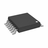
AD5280BRUZ200 Analog Devices Inc, AD5280BRUZ200 Datasheet - Page 23

AD5280BRUZ200
Manufacturer Part Number
AD5280BRUZ200
Description
IC,Digital Potentiometer,TSSOP,14PIN,PLASTIC
Manufacturer
Analog Devices Inc
Datasheet
1.AD5280BRUZ50.pdf
(28 pages)
Specifications of AD5280BRUZ200
Taps
256
Resistance (ohms)
200K
Number Of Circuits
1
Temperature Coefficient
30 ppm/°C Typical
Memory Type
Volatile
Interface
I²C, 2-Wire Serial
Voltage - Supply
4.5 V ~ 16.5 V, ±4.5 V ~ 5.5 V
Operating Temperature
-40°C ~ 85°C
Mounting Type
Surface Mount
Package / Case
14-TSSOP
Resistance In Ohms
200K
Lead Free Status / RoHS Status
Lead free / RoHS Compliant
PROGRAMMABLE LOW-PASS FILTER
In analog-to-digital conversion applications, it is common to
include an antialiasing filter to band-limit the sampling signal.
Dual-channel digital potentiometers can be used to construct
a second-order Sallen key low-pass filter (see Figure 63). The
design equations are
Users can first select some convenient values for the capacitors.
To achieve maximally flat bandwidth where Q = 0.707, let C1 be
twice the size of C2 and let R1 = R2. As a result, R1 and R2 can be
adjusted to the same settings to achieve the desirable bandwidth.
PROGRAMMABLE OSCILLATOR
In a classic Wien-bridge oscillator (Figure 64), the Wien
network (R, R', C, C') provides positive feedback, while R1
and R2 provide negative feedback. At the resonant frequency, f
the overall phase shift is 0, and the positive feedback causes the
circuit to oscillate. With R = R', C = C', and R2 = R2
R
where R is equal to R
diode
), the oscillation frequency is
ω
Q
ω
R
V
V
O
O
O
i
=
=
=
=
=
R1C1
V
256
I
RC
S
1
1
256
2
R1R2C1C2
−
+
or
SAME SETTING
ADJUSTED TO
+
A
D
ω
R
Q
Figure 63. Sallen Key Low-Pass Filter
R1
ω
1
R2C2
O
f
R
O
W
o
B
S
1
AB
2
=
WA
+
2
ω
such that
π
A
R
1
O
RC
R2
2
W
C2
B
C
C1
C
AD8601
+2.5V
–2.5V
V+
V–
U
1
A
V
//(R2
O
B
+
(11)
(12)
(13)
(14)
(15)
Rev. C | Page 23 of 28
O
,
At resonance, setting the following balances the bridge:
In practice, R2/R1 should be set slightly larger than 2 to ensure
that oscillation can start. On the other hand, the alternate turn-
on of Diode D1 and Diode D2 ensures that R2/R1 are smaller
than 2 momentarily and, therefore, stabilizes the oscillation.
Once the frequency is set, the oscillation amplitude can be
tuned by R2
V
selection of R2
converges. R2
increase the amplitude, but the total resistance cannot be
too large to prevent saturation of the output.
O
, I
D
R2
2
3
R1
, and V
V
Figure 64. Programmable Oscillator with Amplitude Control
O
=
2.2nF
R1 = R1
D1 = D2 = 1N4148
=
2
B
I
D
C
because
B
D
are interdependent variables. With proper
B
can be in series with a discrete resistor to
R2
, an equilibrium is reached such that V
I
ADJUSTMENT
= R2B = AD5282
FREQUENCY
10kΩ
B
+
R
V
B
A
D
W
1kΩ
VN
R1
VP
B
W
OP1177
10kΩ
+2.5V
–2.5V
R2
2.2nF
C
B
I
A
V+
V–
2.1kΩ
AD5280/AD5282
R2
AMPLITUDE
ADJUSTMENT
A
A
W
U
10kΩ
1
R
I
B
D1
D2
V
O
O
(16)
(17)


