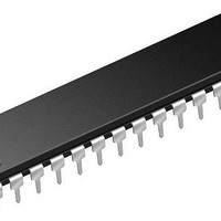
PIC16LF1518-E/SP Microchip Technology, PIC16LF1518-E/SP Datasheet - Page 336

PIC16LF1518-E/SP
Manufacturer Part Number
PIC16LF1518-E/SP
Description
28-pin, 28KB Flash, 1024B RAM, 10-bit ADC, 2xCCP, SPI, MI2C, EUSART, 1.8V-3.6V 2
Manufacturer
Microchip Technology
Series
PIC® XLP™ 16Fr
Datasheet
1.PIC16LF1517-IPT.pdf
(344 pages)
Specifications of PIC16LF1518-E/SP
Core Processor
PIC
Core Size
8-Bit
Speed
20MHz
Connectivity
I²C, LIN, SPI, UART/USART
Peripherals
Brown-out Detect/Reset, POR, PWM, WDT
Number Of I /o
25
Program Memory Size
28KB (16K x 14)
Program Memory Type
FLASH
Ram Size
1K x 8
Voltage - Supply (vcc/vdd)
1.8 V ~ 3.6 V
Data Converters
A/D 17x10b
Oscillator Type
Internal
Operating Temperature
-40°C ~ 125°C
Package / Case
*
Processor Series
PIC16LF151x
Core
PIC
Data Bus Width
8 bit
Data Ram Size
1 KB
Interface Type
I2C, SPI, USART
Maximum Clock Frequency
20 MHz
Number Of Programmable I/os
25
Number Of Timers
3
Operating Supply Voltage
1.8 V to 3.6 V
Maximum Operating Temperature
+ 125 C
Mounting Style
Through Hole
Lead Free Status / RoHS Status
Lead free / RoHS Compliant
Eeprom Size
-
Lead Free Status / Rohs Status
Details
- Current page: 336 of 344
- Download datasheet (3Mb)
PIC16(L)F1516/7/8/9
Clock Switching................................................................... 59
Code Examples
Comparators
Compare Module. See Capture/Compare/PWM (CCP)
CONFIG1 Register.............................................................. 46
CONFIG2 Register.............................................................. 48
Core Function Register ....................................................... 33
Customer Change Notification Service ............................. 341
Customer Notification Service........................................... 341
Customer Support ............................................................. 341
D
Data Memory....................................................................... 24
DC and AC Characteristics ............................................... 311
DC Characteristics
Development Support ....................................................... 313
Device Configuration........................................................... 45
Device ID Register .............................................................. 50
Device Overview ........................................................... 13, 93
E
Effects of Reset
Electrical Specifications .................................................... 283
Enhanced Mid-range CPU .................................................. 19
Enhanced Universal Synchronous Asynchronous
Errata .................................................................................. 11
EUSART............................................................................ 237
DS41452A-page 336
Internal Modes ............................................................ 56
A/D Conversion ......................................................... 146
Changing Between Capture Prescalers .................... 176
Initializing PORTA ..................................................... 115
Initializing PORTB ..................................................... 119
Initializing PORTC..................................................... 122
Initializing PORTD..................................................... 125
Initializing PORTE ..................................................... 128
Writing to Flash Program Memory ............................ 106
C2OUT as T1 Gate ................................................... 161
Extended and Industrial ............................................ 292
Industrial and Extended ............................................ 285
Code Protection .......................................................... 49
Configuration Word ..................................................... 45
User ID .................................................................. 49, 50
PWM mode ............................................................... 183
Receiver Transmitter (EUSART)............................... 237
Associated Registers
Asynchronous Mode ................................................. 239
Baud Rate Generator (BRG)
XT ....................................................................... 53
HFINTOSC.......................................................... 56
Internal Oscillator Clock Switch Timing............... 57
LFINTOSC .......................................................... 56
Baud Rate Generator........................................ 250
12-bit Break Transmit and Receive................... 257
Associated Registers
Auto-Wake-up on Break.................................... 255
Baud Rate Generator (BRG)............................. 249
Clock Accuracy ................................................. 246
Receiver............................................................ 242
Setting up 9-bit Mode with Address Detect....... 244
Transmitter........................................................ 239
Auto Baud Rate Detect ..................................... 254
Baud Rate Error, Calculating ............................ 249
Baud Rates, Asynchronous Modes................... 251
Formulas ........................................................... 250
Receive ..................................................... 245
Transmit .................................................... 241
Preliminary
Extended Instruction Set
F
Fail-Safe Clock Monitor ...................................................... 62
Firmware Instructions ....................................................... 269
Fixed Voltage Reference (FVR)........................................ 137
Flash Program Memory ...................................................... 97
FSR Register ...................................................................... 33
FVRCON (Fixed Voltage Reference Control) Register..... 138
I
I
INDF Register ..................................................................... 33
Indirect Addressing ............................................................. 41
Instruction Format............................................................. 270
Instruction Set................................................................... 269
2
C Mode (MSSP)
Synchronous Master Mode............................... 258, 262
Synchronous Slave Mode
ADDFSR ................................................................... 273
Fail-Safe Condition Clearing....................................... 62
Fail-Safe Detection ..................................................... 62
Fail-Safe Operation..................................................... 62
Reset or Wake-up from Sleep .................................... 62
Associated Registers ................................................ 138
Associated Registers ................................................ 112
Configuration Word w/ Flash Program Memory........ 112
Erasing ..................................................................... 101
Modifying .................................................................. 107
Write Verify ............................................................... 109
Writing ...................................................................... 103
Acknowledge Sequence Timing ............................... 224
Bus Collision
Effects of a Reset ..................................................... 225
I
Master Mode
Multi-Master Communication, Bus Collision and
Multi-Master Mode .................................................... 225
Read/Write Bit Information (R/W Bit) ........................ 201
Slave Mode
Sleep Operation........................................................ 225
Stop Condition Timing .............................................. 224
ADDLW..................................................................... 273
ADDWF..................................................................... 273
ADDWFC .................................................................. 273
ANDLW..................................................................... 273
ANDWF..................................................................... 273
BRA .......................................................................... 274
2
C Clock Rate w/BRG.............................................. 231
High Baud Rate Select (BRGH Bit) .................. 249
Associated Registers
Reception ......................................................... 260
Transmission .................................................... 258
Associated Registers
Reception ......................................................... 263
Transmission .................................................... 262
During a Repeated Start Condition................... 228
During a Stop Condition ................................... 229
Operation.......................................................... 216
Reception ......................................................... 222
Start Condition Timing .............................. 218, 219
Transmission .................................................... 220
Arbitration ......................................................... 225
Transmission .................................................... 206
Receive .................................................... 261
Transmit.................................................... 259
Receive .................................................... 263
Transmit.................................................... 262
2010 Microchip Technology Inc.
Related parts for PIC16LF1518-E/SP
Image
Part Number
Description
Manufacturer
Datasheet
Request
R

Part Number:
Description:
IC, 8BIT MCU, PIC16LF, 32MHZ, QFN-28
Manufacturer:
Microchip Technology
Datasheet:

Part Number:
Description:
IC, 8BIT MCU, PIC16LF, 32MHZ, QFN-28
Manufacturer:
Microchip Technology
Datasheet:

Part Number:
Description:
IC, 8BIT MCU, PIC16LF, 32MHZ, DIP-18
Manufacturer:
Microchip Technology
Datasheet:

Part Number:
Description:
IC, 8BIT MCU, PIC16LF, 20MHZ, TQFP-44
Manufacturer:
Microchip Technology
Datasheet:

Part Number:
Description:
7 KB Flash, 384 Bytes RAM, 32 MHz Int. Osc, 16 I/0, Enhanced Mid Range Core, Nan
Manufacturer:
Microchip Technology

Part Number:
Description:
14KB Flash, 512B RAM, LCD, 11x10b ADC, EUSART, NanoWatt XLP 28 SOIC .300in T/R
Manufacturer:
Microchip Technology
Datasheet:

Part Number:
Description:
14KB Flash, 512B RAM, LCD, 11x10b ADC, EUSART, NanoWatt XLP 28 SSOP .209in T/R
Manufacturer:
Microchip Technology
Datasheet:

Part Number:
Description:
MCU PIC 14KB FLASH XLP 28-SSOP
Manufacturer:
Microchip Technology

Part Number:
Description:
MCU PIC 14KB FLASH XLP 28-SOIC
Manufacturer:
Microchip Technology

Part Number:
Description:
MCU PIC 512B FLASH XLP 28-UQFN
Manufacturer:
Microchip Technology

Part Number:
Description:
MCU PIC 14KB FLASH XLP 28-SPDIP
Manufacturer:
Microchip Technology

Part Number:
Description:
MCU 7KB FLASH 256B RAM 40-UQFN
Manufacturer:
Microchip Technology

Part Number:
Description:
MCU 7KB FLASH 256B RAM 44-TQFP
Manufacturer:
Microchip Technology

Part Number:
Description:
MCU 14KB FLASH 1KB RAM 28-UQFN
Manufacturer:
Microchip Technology

Part Number:
Description:
MCU PIC 14KB FLASH XLP 40-UQFN
Manufacturer:
Microchip Technology


