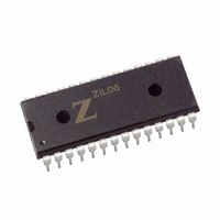
Z84C3006PEG Zilog, Z84C3006PEG Datasheet - Page 40

Z84C3006PEG
Manufacturer Part Number
Z84C3006PEG
Description
IC 6MHZ Z80 CMOS CTC 28-PDIP
Manufacturer
Zilog
Type
Counter/Timer Circuit (CTC)r
Series
Z80r
Specifications of Z84C3006PEG
Frequency
6MHz
Voltage - Supply
4.5 V ~ 5.5 V
Current - Supply
8mA
Operating Temperature
-40°C ~ 100°C
Package / Case
28-DIP (0.600", 15.24mm)
Processor Series
Z84C3xx
Core
Z80
Data Bus Width
8 bit
Maximum Clock Frequency
6 MHz
Operating Supply Voltage
0 V to 5 V
Maximum Operating Temperature
+ 100 C
Mounting Style
Through Hole
Minimum Operating Temperature
- 40 C
Filter Terminals
SMD
Ic Generic Number
84C30
Operating Temperature Min
-40°C
Operating Temperature Max
100°C
Clock Frequency
6MHz
Rohs Compliant
Yes
Cpu Speed
6MHz
Digital Ic Case Style
DIP
No. Of Pins
28
Supply Voltage Range
5V
Operating Temperature Range
-40°C To +100°C
Lead Free Status / RoHS Status
Lead free / RoHS Compliant
Count
-
Lead Free Status / Rohs Status
Details
Other names
269-3910
Z84C3006PEG
Z84C3006PEG
Available stocks
Company
Part Number
Manufacturer
Quantity
Price
Company:
Part Number:
Z84C3006PEG
Manufacturer:
ZILOG
Quantity:
1 980
Company:
Part Number:
Z84C3006PEG
Manufacturer:
Zilog
Quantity:
1 722
Company:
Part Number:
Z84C3006PEG
Manufacturer:
ZILOG
Quantity:
1 980
Company:
Part Number:
Z84C3006PEG
Manufacturer:
WSI
Quantity:
4 970
Part Number:
Z84C3006PEG
Manufacturer:
ZILOG
Quantity:
20 000
- Current page: 40 of 308
- Download datasheet (2Mb)
20
UM008005-0205
Z80 CPU
User’s Manual
Power-Down Release Cycle
RESET
HALT
HALT
CLK
NMI
M1
CLK
The system clock must be supplied to the CMOS Z80 CPU to release the
power-down state. When the system clock is supplied to the CLK input, the
CMOS Z80 CPU restarts operations from the point at which the power-
down state was implemented. The timing diagrams for the release from
power-down mode are featured in Figure 13 , 14 and 15.
When the HALT instruction is executed to enter the power-down state, the
CMOS Z80 CPU also enters the HALT state. An interrupt signal (either
NMI or ANT) or a RESET signal must be applied to the CPU after the
system clock is supplied in order to release the power-down state.
Figure 13. Power-Down Release Cycle No. 1
Figure 14. Power-Down Release Cycle No. 2
M1
T
1
T
2
T
3
T
4
T
1
T
1
T
2
T
3
Overview
T
4
Related parts for Z84C3006PEG
Image
Part Number
Description
Manufacturer
Datasheet
Request
R

Part Number:
Description:
Communication Controllers, ZILOG INTELLIGENT PERIPHERAL CONTROLLER (ZIP)
Manufacturer:
Zilog, Inc.
Datasheet:

Part Number:
Description:
KIT DEV FOR Z8 ENCORE 16K TO 64K
Manufacturer:
Zilog
Datasheet:

Part Number:
Description:
KIT DEV Z8 ENCORE XP 28-PIN
Manufacturer:
Zilog
Datasheet:

Part Number:
Description:
DEV KIT FOR Z8 ENCORE 8K/4K
Manufacturer:
Zilog
Datasheet:

Part Number:
Description:
KIT DEV Z8 ENCORE XP 28-PIN
Manufacturer:
Zilog
Datasheet:

Part Number:
Description:
DEV KIT FOR Z8 ENCORE 4K TO 8K
Manufacturer:
Zilog
Datasheet:

Part Number:
Description:
CMOS Z8 microcontroller. ROM 16 Kbytes, RAM 256 bytes, speed 16 MHz, 32 lines I/O, 3.0V to 5.5V
Manufacturer:
Zilog, Inc.
Datasheet:

Part Number:
Description:
Low-cost microcontroller. 512 bytes ROM, 61 bytes RAM, 8 MHz
Manufacturer:
Zilog, Inc.
Datasheet:

Part Number:
Description:
Z8 4K OTP Microcontroller
Manufacturer:
Zilog, Inc.
Datasheet:

Part Number:
Description:
CMOS SUPER8 ROMLESS MCU
Manufacturer:
Zilog, Inc.
Datasheet:

Part Number:
Description:
SL1866 CMOSZ8 OTP Microcontroller
Manufacturer:
Zilog, Inc.
Datasheet:

Part Number:
Description:
SL1866 CMOSZ8 OTP Microcontroller
Manufacturer:
Zilog, Inc.
Datasheet:

Part Number:
Description:
OTP (KB) = 1, RAM = 125, Speed = 12, I/O = 14, 8-bit Timers = 2, Comm Interfaces Other Features = Por, LV Protect, Voltage = 4.5-5.5V
Manufacturer:
Zilog, Inc.
Datasheet:

Part Number:
Description:
Manufacturer:
Zilog, Inc.
Datasheet:


