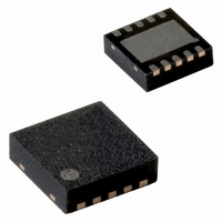
PCA8565BS/1,118 NXP Semiconductors, PCA8565BS/1,118 Datasheet - Page 15

PCA8565BS/1,118
Manufacturer Part Number
PCA8565BS/1,118
Description
IC CMOS RTC/CALENDAR 8-HVSON
Manufacturer
NXP Semiconductors
Type
Clock/Calendarr
Datasheet
1.PCA8565TS1118.pdf
(39 pages)
Specifications of PCA8565BS/1,118
Time Format
HH:MM:SS (24 hr)
Date Format
YY-MM-DD-dd
Interface
I²C, 2-Wire Serial
Voltage - Supply
1.8 V ~ 5.5 V
Operating Temperature
-40°C ~ 125°C
Mounting Type
Surface Mount
Package / Case
10-HVSON
Bus Type
Serial (2-Wire, I2C)
Operating Supply Voltage (typ)
2.5/3.3/5V
Operating Supply Voltage (max)
5.5V
Operating Supply Voltage (min)
1.8V
Operating Temperature (min)
-40C
Pin Count
10
Mounting
Surface Mount
Lead Free Status / RoHS Status
Lead free / RoHS Compliant
Memory Size
-
Lead Free Status / Rohs Status
Compliant
Other names
935282254118
PCA8565BS/1-T
PCA8565BS/1-T
PCA8565BS/1-T
PCA8565BS/1-T
Available stocks
Company
Part Number
Manufacturer
Quantity
Price
Company:
Part Number:
PCA8565BS/1,118
Manufacturer:
NXP
Quantity:
9 001
NXP Semiconductors
PCA8565_2
Product data sheet
9.7.1 Register Timer_control
9.8.1 Bits TF and AF
9.8 Interrupt output
Table 24.
[1]
[2]
The timer register is an 8-bit binary countdown timer. It is enabled and disabled via the
bit TE in register Timer_control. The source clock for the timer is also selected by the
TD[1:0] in register Timer_control. Other timer properties such as interrupt generation are
controlled via register Control_2.
For accurate read back of the countdown value, the I
frequency of at least twice the selected timer clock. Since it is not possible to freeze the
countdown timer counter during read back, it is recommended to read the register twice
and check for consistent results.
Table 25.
When an alarm occurs, AF is set to 1. Similarly, at the end of a timer countdown, TF is
set to 1. These bits maintain their value until overwritten using the interface. If both timer
and alarm interrupts are required in the application, the source of the interrupt is
determined by reading these bits. To prevent one flag being overwritten while clearing
another a logic AND is performed during a write access.
Bit
7
6 to 2 -
1 to 0 TD[1:0]
Bit
7 to 0 COUNTDOWN_TIMER 00h to FFh countdown value = n;
Default value.
These bits determine the source clock for the countdown timer; when not in use, TD[1:0] should be set to
1
60
Symbol
TE
Hz for power saving.
Symbol
Register Timer_control (address 0Eh) bits description
Timer (address 0Fh) bits description
Rev. 02 — 16 June 2009
Value
0
1
-
00
01
10
11
[1]
[2]
Value
Description
timer is disabled
timer is enabled
unused
timer source clock frequency select
4.096 kHz
64 Hz
1 Hz
1
60
Hz
Description
CountdownPeriod
2
C-bus clock (SCL) must operate at a
=
-------------------------------------------------------------- -
SourceClockFrequency
Real time clock/calendar
[2]
PCA8565
© NXP B.V. 2009. All rights reserved.
n
15 of 39


