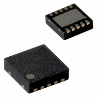
PCA8565BS/1,118 NXP Semiconductors, PCA8565BS/1,118 Datasheet - Page 18

PCA8565BS/1,118
Manufacturer Part Number
PCA8565BS/1,118
Description
IC CMOS RTC/CALENDAR 8-HVSON
Manufacturer
NXP Semiconductors
Type
Clock/Calendarr
Datasheet
1.PCA8565TS1118.pdf
(39 pages)
Specifications of PCA8565BS/1,118
Time Format
HH:MM:SS (24 hr)
Date Format
YY-MM-DD-dd
Interface
I²C, 2-Wire Serial
Voltage - Supply
1.8 V ~ 5.5 V
Operating Temperature
-40°C ~ 125°C
Mounting Type
Surface Mount
Package / Case
10-HVSON
Bus Type
Serial (2-Wire, I2C)
Operating Supply Voltage (typ)
2.5/3.3/5V
Operating Supply Voltage (max)
5.5V
Operating Supply Voltage (min)
1.8V
Operating Temperature (min)
-40C
Pin Count
10
Mounting
Surface Mount
Lead Free Status / RoHS Status
Lead free / RoHS Compliant
Memory Size
-
Lead Free Status / Rohs Status
Compliant
Other names
935282254118
PCA8565BS/1-T
PCA8565BS/1-T
PCA8565BS/1-T
PCA8565BS/1-T
Available stocks
Company
Part Number
Manufacturer
Quantity
Price
Company:
Part Number:
PCA8565BS/1,118
Manufacturer:
NXP
Quantity:
9 001
NXP Semiconductors
PCA8565_2
Product data sheet
9.12 STOP bit function
The signal applied to pin CLKOUT should have a minimum pulse width of 300 ns and a
minimum period of 1000 ns. The internal 64 Hz clock, now sourced from CLKOUT, is
divided down to 1 Hz by a 2
into a known state by using bit STOP. When bit STOP is set, the pre-scaler is reset to 0
(STOP must be cleared before the pre-scaler can operate again).
From a STOP condition, the first 1 second increment will take place after 32 positive
edges on CLKOUT. Thereafter, every 64 positive edges will cause a 1 second increment.
Remark: Entry into EXT_CLK test mode is not synchronized to the internal 64 Hz clock.
When entering the test mode, no assumption as to the state of the pre-scaler can be
made.
Operation example:
Repeat 7 and 8 for additional increments.
The function of the STOP bit is to allow for accurate starting of the time circuits. The STOP
bit function will cause the upper part of the prescaler (F
thus no 1 Hz ticks will be generated (see
will not increment until the STOP bit is released (see
1. Set EXT_CLK test mode (Control_1, bit TEST1 = 1).
2. Set STOP (Control_1, bit STOP = 1).
3. Clear STOP (Control_1, bit STOP = 0).
4. Set time registers to desired value.
5. Apply 32 clock pulses to CLKOUT.
6. Read time registers to see the first change.
7. Apply 64 clock pulses to CLKOUT.
8. Read time registers to see the second change.
Fig 10. STOP bit
OSC
Rev. 02 — 16 June 2009
F
6
0
divide chain called a pre-scaler. The pre-scaler can be set
F
1
DETECTOR
OSC STOP
Figure
RES
F
10). The time circuits can then be set and
2
32768 Hz
1024 Hz
reset
Figure 11
32 Hz
1 Hz
2
to F
14
RES
F
13
) to be held in reset and
Real time clock/calendar
and
CLKOUT source
Table
RES
PCA8565
F
© NXP B.V. 2009. All rights reserved.
14
28).
013aaa089
1 Hz tick
stop
18 of 39


