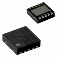
PCA8565BS/1,118 NXP Semiconductors, PCA8565BS/1,118 Datasheet - Page 16

PCA8565BS/1,118
Manufacturer Part Number
PCA8565BS/1,118
Description
IC CMOS RTC/CALENDAR 8-HVSON
Manufacturer
NXP Semiconductors
Type
Clock/Calendarr
Datasheet
1.PCA8565TS1118.pdf
(39 pages)
Specifications of PCA8565BS/1,118
Time Format
HH:MM:SS (24 hr)
Date Format
YY-MM-DD-dd
Interface
I²C, 2-Wire Serial
Voltage - Supply
1.8 V ~ 5.5 V
Operating Temperature
-40°C ~ 125°C
Mounting Type
Surface Mount
Package / Case
10-HVSON
Bus Type
Serial (2-Wire, I2C)
Operating Supply Voltage (typ)
2.5/3.3/5V
Operating Supply Voltage (max)
5.5V
Operating Supply Voltage (min)
1.8V
Operating Temperature (min)
-40C
Pin Count
10
Mounting
Surface Mount
Lead Free Status / RoHS Status
Lead free / RoHS Compliant
Memory Size
-
Lead Free Status / Rohs Status
Compliant
Other names
935282254118
PCA8565BS/1-T
PCA8565BS/1-T
PCA8565BS/1-T
PCA8565BS/1-T
Available stocks
Company
Part Number
Manufacturer
Quantity
Price
Company:
Part Number:
PCA8565BS/1,118
Manufacturer:
NXP
Quantity:
9 001
NXP Semiconductors
PCA8565_2
Product data sheet
Fig 8.
COUNTDOWN COUNTER
When bits TIE and AIE are disabled, pin INT will remain high-impedance.
Interrupt scheme
9.8.2 Bits TIE and AIE
9.8.3 Countdown timer interrupts
TE
9.9 Clock output
These bits activate or deactivate the generation of an interrupt when TF or AF is asserted
respectively. The interrupt is the logical OR of these two conditions when both AIE and
TIE are set.
The pulse generator for the countdown timer interrupt uses an internal clock and is
dependent on the selected source clock for the countdown timer and on the countdown
value n. As a consequence, the width of the interrupt pulse varies (see
Table 26.
[1]
A programmable square wave is available at pin CLKOUT. Operation is controlled by the
CLKOUT_control register at address 0Dh. Frequencies of 32.768 kHz (default),
1.024 kHz, 32 Hz and 1 Hz can be generated for use as a system clock, microcontroller
clock, input to a charge pump, or for calibration of the oscillator. CLKOUT is an open-drain
output and enabled at power-on. If disabled it becomes high-impedance.
Source clock (Hz)
4096
64
1
1
60
from interface:
from interface:
n = loaded countdown value. Timer stopped when n = 0.
set alarm
clear AF
clear TF
flag, AF
INT operation (bit TI_TP = 1)
SET
SET
AF: ALARM
TF: TIMER
CLEAR
CLEAR
FLAG
Rev. 02 — 16 June 2009
INT period (s)
n = 1
1
1
1
1
TRIGGER
8192
128
64
64
GENERATOR 2
[1]
PULSE
CLEAR
to interface:
read TF
to interface:
read AF
TI_TP
0
1
n > 1
1
1
1
1
AIE
TIE
4096
64
64
64
Real time clock/calendar
013aaa087
PCA8565
© NXP B.V. 2009. All rights reserved.
Table
E.G.AIE
INT
26).
0
1
16 of 39


