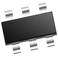
PIC10F220-E/OT Microchip Technology, PIC10F220-E/OT Datasheet - Page 55

PIC10F220-E/OT
Manufacturer Part Number
PIC10F220-E/OT
Description
384B Flash, 16B RAM, 4 I/O, 8bit ADC 6 SOT-23 BAG
Manufacturer
Microchip Technology
Series
PIC® 10Fr
Datasheet
1.PIC10F220-IMC.pdf
(86 pages)
Specifications of PIC10F220-E/OT
Processor Series
PIC10F
Core
RISC
Data Bus Width
8 bit
Program Memory Type
Flash
Program Memory Size
256 B
Data Ram Size
16 B
Interface Type
RS-232, USB
Maximum Clock Frequency
8 MHZ
Number Of Programmable I/os
4
Number Of Timers
1
Maximum Operating Temperature
+ 125 C
Mounting Style
SMD/SMT
Package / Case
SOT-23-6
Operating Temperature Range
- 40 C to + 125 C
Processor To Be Evaluated
PIC10F220
Supply Current (max)
100 nA
Core Processor
PIC
Core Size
8-Bit
Speed
8MHz
Connectivity
-
Peripherals
POR, WDT
Number Of I /o
4
Eeprom Size
-
Ram Size
16 x 8
Voltage - Supply (vcc/vdd)
2 V ~ 5.5 V
Data Converters
A/D 2x8b
Oscillator Type
Internal
Operating Temperature
-40°C ~ 125°C
Lead Free Status / Rohs Status
Details
10.1
© 2007 Microchip Technology Inc.
DC CHARACTERISTICS
D001
D002
D003
D004
D010
D020
D022
Note 1:
Param
No.
2:
3:
4:
*
DC Characteristics: PIC10F220/222 (Industrial)
V
S
Sym
I
V
V
I
WDT
I
POR
VDD
DD
PD
These parameters are characterized but not tested.
Data in the Typical (“Typ”) column is based on characterization results at 25°C. This data is for design guidance only
and is not tested.
This is the limit to which V
The supply current is mainly a function of the operating voltage and frequency. Other factors such as bus loading, bus
rate, internal code execution pattern and temperature also have an impact on the current consumption.
a) The test conditions for all I
Power-down current is measured with the part in Sleep mode, with all I/O pins in high-impedance state and tied to V
or V
enabled.
DD
DR
b) For standby current measurements, the conditions are the same, except that the device is in Sleep mode.
All I/O pins tri-stated, pulled to V
SS
Supply Voltage
RAM Data Retention Voltage
V
to ensure Power-on Reset
V
to ensure Power-on Reset
Supply Current
Power-down Current
WDT Current
. The peripheral current is the sum of the base I
DD
DD
Start Voltage
Rise Rate
Characteristic
(4)
(3)
DD
(4)
can be lowered in Sleep mode without losing RAM data.
DD
measurements in active operation mode are:
(2)
SS
, T0CKI = V
Standard Operating Conditions (unless otherwise specified)
Operating Temperature -40×C ≤ T
0.05*
Min
1.5*
2.0
—
—
—
—
—
—
—
—
—
DD
Typ
0.625
0.800
, MCLR = V
175
250
Vss
0.1
1.0
PD
—
—
1
7
(1)
and the additional current consumed when the peripheral is
Max
275
400
5.5
1.1
1.5
1.2
2.4
16
—
—
—
3
DD
; WDT enabled/disabled as specified.
Units
V/ms
mA
mA
μA
μA
μA
μA
μA
μA
V
V
V
PIC10F220/222
See Figure 10-1
Device in Sleep mode
V
V
V
V
V
V
V
V
DD
DD
DD
DD
DD
DD
DD
DD
A
≤ +85°C (industrial)
= 2.0V, Fosc = 4 MHz
= 5.0V, Fosc = 4 MHz
= 2.0V, Fosc = 8 MHz
= 5.0V, Fosc = 8 MHz
= 2.0V
= 5.0V
= 2.0V
= 5.0V
Conditions
DS41270E-page 53
DD


