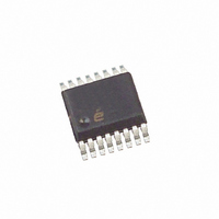
EL9110IUZ Intersil, EL9110IUZ Datasheet - Page 7

EL9110IUZ
Manufacturer Part Number
EL9110IUZ
Description
IC RECEIVR/EQUALIZER DIFF 16QSOP
Manufacturer
Intersil
Type
Receiverr
Datasheet
1.EL9110IUZ.pdf
(10 pages)
Specifications of EL9110IUZ
Number Of Drivers/receivers
0/1
Protocol
Twisted-Pair
Voltage - Supply
5V
Mounting Type
Surface Mount
Package / Case
16-QSOP
Device Type
Transceiver
Driver Case Style
QSOP
No. Of Pins
16
Operating Temperature Range
-40°C To +85°C
Filter Terminals
SMD
Transceiver Type
Differential
Rohs Compliant
Yes
Current Rating
60A
Frequency
150GHz
Lead Free Status / RoHS Status
Lead free / RoHS Compliant
Available stocks
Company
Part Number
Manufacturer
Quantity
Price
Part Number:
EL9110IUZ
Manufacturer:
INTERSIL
Quantity:
20 000
Company:
Part Number:
EL9110IUZ-T7
Manufacturer:
Intersil
Quantity:
2 000
operation it is anticipated the X2 mode will be selected and
the output load will be back matched. A unity gain to the
output load will then be achieved with a gain control voltage
of about 0.35V. This allows the gain to be trimmed up or
down by 6dB to compensate for any gain/loss errors that
affect the contrast of the video signal. Figure 12 shows an
example plot of the gain to the load with gain control voltage.
FIGURE 13. CAT-5 CABLE ATTENUATION CHARACTERISTICS
FIGURE 12. VARIATION OF GAIN WITH GAIN CONTROL
70
60
50
40
30
20
10
0
0.01M
2.0
1.8
1.6
1.4
1.2
1.0
0.8
0.6
0.4
0
VOLTAGE
0.10M
0.2
50M
FREQUENCY (Hz)
0.4
100M
200M
V
7
1M
300M
GAIN
0.6
10M
0.8
1.0
100M
EL9110
Circuit and Layout Recommendation
The interconnection cable is a transmission line therefore for
proper function it should be treated like transmission line, a
refection-free termination is necessary.
A reflection-free termination is a real "ohmic" resistor with as
less as possible reactive parasitic.
The traces of the layout, up to the point where of the
termination resistor placed, are part of the transmission line
which also includes the cable's connector. A connector with
a better controlled impedance is an obligation for good
picture quality. The termination resistor should be placed
close to the inputs of the device's pins (pin 3 and pin 4.) The
small capacitance differential and common mode
capacitance of the input pins of the device makes it possible
to connect parallel to the termination resistor.
The cable will work as an antenna for all the RF spectrum
which is "in the air" where the cable is used. The spectrum,
particularly its common mode components, could and will
contain high energy level of transients which are above the
built-in protection level of the device and easily could
damage its inputs. Using a transient protection circuit
according to the given application is recommended.
Since the used signal's bandwidth is in the range of 100MHz,
for layout and power supply bypassing the roles of RF
design should be applied.
The following picture is taken from the DB9110 demo-
board's layout. For better visibility the ground plain is
removed.
The ground plane is shown in Figure 14.
FIGURE 14. DEMO BOARD LAYOUT
November 30, 2007
FN7305.5


