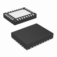
EL9111ILZ-T7 Intersil, EL9111ILZ-T7 Datasheet - Page 5

EL9111ILZ-T7
Manufacturer Part Number
EL9111ILZ-T7
Description
IC DIFF RCVR/EQUALZR TRPL 28-QFN
Manufacturer
Intersil
Type
Receiverr
Datasheet
1.EL9111ILZ.pdf
(13 pages)
Specifications of EL9111ILZ-T7
Number Of Drivers/receivers
0/3
Protocol
Twisted-Pair
Voltage - Supply
5V
Mounting Type
Surface Mount
Package / Case
28-VQFN
Lead Free Status / RoHS Status
Lead free / RoHS Compliant
Available stocks
Company
Part Number
Manufacturer
Quantity
Price
Company:
Part Number:
EL9111ILZ-T7
Manufacturer:
Intersil
Quantity:
98
Part Number:
EL9111ILZ-T7
Manufacturer:
INTERSIL
Quantity:
20 000
Pin Descriptions
Typical Performance Curves
NUMBER
FIGURE 1. FREQUENCY RESPONSE OF ALL CHANNELS
FIGURE 3. GAIN vs FREQUENCY FOR VARIOUS V
PIN
21
22
23
24
25
26
27
28
Thermal Pad
-1
-3
-5
5
3
1
1M
X
V
V
R
PIN NAME
SYNCREF
2
GAIN
CTRL
LOAD
EL9111IL
ENABLE
=LOW
VINM_B
HOUT
VOUT
VSP
X2
0V
=0V
=0V
=150Ω
FREQUENCY (Hz)
(Continued)
Blue negative differential input
+5V to core of chip
Decoded Horizontal sync referenced to
SYNCREF
Decoded Vertical sync referenced to SYNCREF
Reference level for H
Logic signal for x1/x2 output gain setting
Chip enable logic signal
0V reference for output voltage
Must be connected to -5V
10M
5
PIN FUNCTION
EL9111IL
100M 200M
OUT
and V
CTRL
EL9111, EL9112
OUT
logic outputs
FIGURE 4. GAIN vs FREQUENCY FOR VARIOUS V
PIN NAME
EL9112IL
ENABLE
VINM_B
VCM_R
VCM_G
VCM_B
FIGURE 2. GAIN vs FREQUENCY ALL CHANNELS
VSP
X2
0V
V
GAIN
Blue negative differential input
+5V to core of chip
Red common-mode voltage at inputs
Green common-mode voltage at inputs
Blue common-mode voltage at inputs
Logic signal for x1/x2 output gain setting
Chip enable logic signal
0V reference for output voltage
PIN FUNCTION
EL9112IL
CTRL
May 9, 2007
FN7450.4
AND


