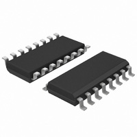
PCA9541D/03,118 NXP Semiconductors, PCA9541D/03,118 Datasheet - Page 9

PCA9541D/03,118
Manufacturer Part Number
PCA9541D/03,118
Description
IC I2C 2:1 SELECTOR 16-SOIC
Manufacturer
NXP Semiconductors
Datasheet
1.PCA9541BS03118.pdf
(41 pages)
Specifications of PCA9541D/03,118
Applications
2-Channel I²C Multiplexer
Interface
I²C, SMBus
Voltage - Supply
2.3 V ~ 5.5 V
Package / Case
16-SOIC (3.9mm Width)
Mounting Type
Surface Mount
Lead Free Status / RoHS Status
Lead free / RoHS Compliant
Other names
568-1851-2
935273317118
PCA9541D/03-T
935273317118
PCA9541D/03-T
Available stocks
Company
Part Number
Manufacturer
Quantity
Price
Part Number:
PCA9541D/03,118
Manufacturer:
NXP/恩智浦
Quantity:
20 000
NXP Semiconductors
PCA9541_7
Product data sheet
After a master has sent the bus control request:
Interrupt status can be read. See
information.
1. The previous master is disconnected from the I
2. A built-in bus initialization/recovery function can take temporary control of the
3. When the initialization has been requested and completed, the PCA9541 sends an
4. When the bus initialization/recovery function has not been requested (BUSINIT = 0),
•
•
•
If a master was connected to the downstream bus prior to the disconnect, then an
interrupt is sent on the respective interrupt output in an attempt to let that master
know that it is no longer connected to the downstream bus. This is indicated by setting
the BUSLOST bit in the Interrupt Status Register.
If the combination of the BUSON and the NBUSON bits causes a master to be
connected to the downstream bus and if there is no change in the BUSON bits since
when the disconnect took effect, then the master requesting the bus is connected to
the downstream bus. If it requests a bus initialization sequence, then it is performed.
If there is no change in the combination of the BUSON and the NBUSON bits and a
new master wants the bus, then the downstream bus is disconnected from the old
master that was using it and the new master gets control of it. Again, the bus
initialization if requested is done. The appropriate interrupt signals are generated.
master is sent through its INT line to let it know that it lost control of the bus.
BUSLOST bit in the Interrupt Status Register is set. This interrupt can be masked by
setting the BUSLOSTMSK bit to logic 1.
downstream channel to initialize the bus before making the actual switch to the new
bus master. This function is activated by setting the BUSINIT to logic 1 by the master
during the same write sequence as the one programming MYBUS and BUSON bits.
When activated and whether the bus was previously idle or not:
a. 9 clock pulses are sent on the SCL_SLAVE.
b. SDA_SLAVE line is released (HIGH) when the clock pulses are sent to
c. Finally a STOP condition is sent to the downstream slave channel.
This sequence will complete any read transaction which was previously in process
and the downstream slave configured as a slave-transmitter should release the SDA
line because the PCA9541 did not acknowledge the last byte.
interrupt to the new master through its INT line and connects the new master to the
downstream channel. BUSINIT bit in the Interrupt Status Register is set. The switch
operation occurs after the master asking the bus control has sent a STOP
command. This interrupt can be masked by setting the BUSINITMSK bit to logic 1.
the PCA9541 connects the new master to the slave downstream channel. The switch
operation occurs after the master asking the bus control has sent a STOP
command. PCA9541 sends an interrupt to the new master through its INT line if the
built-in bus sensor function detects a non-idle condition in the downstream slave
channel at the switching time. BUSOK bit in the Interrupt Status Register is set. This
means that a STOP condition has not been detected in the previous bus
communication and that an external bus recovery/initialization must be performed. If
an idle condition has been detected at the switching time, no interrupt will be sent.
This interrupt can be masked by setting the BUSOKMSK bit to logic 1.
SCL_SLAVE. This is equivalent to sending 8 data bits and a not acknowledge.
Rev. 07 — 2 July 2009
2-to-1 I
2
Section 8.4 “Interrupt Status registers”
C-bus master selector with interrupt logic and reset
2
C-bus. An interrupt to the previous
PCA9541
© NXP B.V. 2009. All rights reserved.
for more
9 of 41


