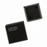
SC26C92C1A,518 NXP Semiconductors, SC26C92C1A,518 Datasheet - Page 18

SC26C92C1A,518
Manufacturer Part Number
SC26C92C1A,518
Description
IC DUART SOT187-2
Manufacturer
NXP Semiconductors
Datasheet
1.SC26C92C1A518.pdf
(31 pages)
Specifications of SC26C92C1A,518
Number Of Channels
2, DUART
Package / Case
44-LCC (J-Lead)
Features
Transceiver
Fifo's
8 Byte
Voltage - Supply
5V
With Auto Flow Control
Yes
With False Start Bit Detection
Yes
With Modem Control
Yes
With Cmos
Yes
Mounting Type
Surface Mount
Data Rate
0.2304 MBd
Supply Voltage (max)
5.5 V
Supply Voltage (min)
4.5 V
Supply Current
10 mA
Maximum Operating Temperature
+ 70 C
Minimum Operating Temperature
0 C
Mounting Style
SMD/SMT
Operating Supply Voltage
5 V
Lead Free Status / RoHS Status
Lead free / RoHS Compliant
Lead Free Status / RoHS Status
Lead free / RoHS Compliant, Lead free / RoHS Compliant
Other names
568-5047-2
935051510518
SC26C92C1A,518
SC26C92C1A-T
SC26C92C1A-T
935051510518
SC26C92C1A,518
SC26C92C1A-T
SC26C92C1A-T
Philips Semiconductors
applied via CRB. After reading or writing MR0B, the pointer will
point to MR1B.
The bit definitions for this register are identical to MR0A, except that
all control actions apply to the Channel B receiver and transmitter
and the corresponding inputs and outputs. MR0B[3:0] are reserved.
MR1B – Channel B Mode Register 1
MR1B is accessed when the Channel B MR pointer points to MR1.
The pointer is set to MR1 by RESET or by a ‘set pointer’ command
applied via CRB. After reading or writing MR1B, the pointer will
point to MR2B.
The bit definitions for this register are identical to MR1A, except that
all control actions apply to the Channel B receiver and transmitter
and the corresponding inputs and outputs.
MR2B – Channel B Mode Register 2
MR2B is accessed when the Channel B MR pointer points to MR2,
which occurs after any access to MR1B. Accesses to MR2B do not
change the pointer.
The bit definitions for mode register are identical to the bit
definitions for MR2A, except that all control actions apply to the
Channel B receiver and transmitter and the corresponding inputs
and outputs.
CSRA – Channel A Clock Select Register
CSRA[7:4] – Channel A Receiver Clock Select
This field selects the baud rate clock for the Channel A receiver.
The field definition is shown in Table 5.
Table 5. Baud Rate
2000 Jan 31
NOTE: The receiver clock is always a 16X clock except for CSRA[7:4] = 1111.
Dual universal asynchronous receiver/transmitter (DUART)
CSRA[7:4]
CSRB[7:4]
0000
0001
0010
0100
0101
1000
1001
1010
0011
0110
0111
1011
1100
1101
1110
1111
1110
1111
ACR[7] = 0
IP4-16X
IP4-1X
MR0[0] = 0 (Normal Mode)
38.4K
Timer
134.5
1,200
1,050
2,400
4,800
7,200
9,600
110
200
300
600
50
IP4-16X
IP4-1X
(Base on a 3.6864MHz crystal clock)
ACR[7] = 0
ACR[7] = 1
IP4-16X
IP4-1X
1,200
2,000
2,400
4,800
1,800
9,600
134.5
Timer
19.2K
110
150
300
600
75
IP4-16X
IP4-1X
ACR[7] = 1
ACR[7] = 0
MR0[0] = 1 (Extended Mode I)
IP4-16X
230.4K
IP4-1X
14.4K
28.8K
57.6K
134.5
1,050
7,200
Timer
1200
1800
3600
7200
300
110
18
The receiver clock is always a 16X clock except for CSRB[7:4] = 1111.
CSRA[3:0] – Channel A Transmitter Clock Select
This field selects the baud rate clock for the Channel A transmitter.
The field definition is as shown in Table 5, except as follows:
The transmitter clock is always a 16X clock except for CSR[3:0] = 1111.
CSRB – Channel B Clock Select Register
CSRB[7:4] – Channel B Receiver Clock Select
This field selects the baud rate clock for the Channel B receiver.
The field definition is as shown in Table 5, except as follows:
The receiver clock is always a 16X clock except for CSRB[7:4] = 1111.
CSRB[3:0] – Channel B Transmitter Clock Select
This field selects the baud rate clock for the Channel B transmitter.
The field definition is as shown in Table 5, except as follows:
The transmitter clock is always a 16X clock except for
CSRB[3:0] = 1111.
CSRA[3:0]
CSRB[7:4]
CSRB[3:0]
1110
1111
1110
1111
1110
1111
ACR[7] = 1
IP4-16X
115.2K
IP4-1X
14.4K
28.8K
57.6K
134.5
7,200
2,000
1,800
Timer
1800
3600
450
110
900
IP3-16X
IP3-1X
IP6-16X
IP6-1X
IP5-16X
IP5-1X
ACR[7] = 0
ACR[7] = 0
ACR[7] = 0
ACR[7] = 0
MR0[2] = 1 (Extended Mode II)
IP4-16X
115.2K
IP4-1X
19.2K
28.8K
57.6K
57.6K
57.6K
38.4K
1,076
1,050
4,800
9,600
Timer
4,800
880
Product specification
SC26C92
IP3-16X
IP3-1X
IP6-16X
IP6-1X
IP5-16X
IP5-1X
ACR[7] = 1
ACR[7] = 1
ACR[7] = 1
ACR[7] = 1
IP4-16X
115.2K
IP4-1X
14.4K
28.8K
57.6K
57.6K
14.4K
19.2K
1,076
2,000
4,800
9,600
Timer
7,200
880


