LM49200TLX/NOPB National Semiconductor, LM49200TLX/NOPB Datasheet - Page 8
LM49200TLX/NOPB
Manufacturer Part Number
LM49200TLX/NOPB
Description
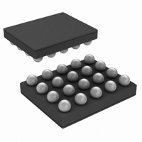
IC AUDIO SUB 1.25W AB 20USMD
Manufacturer
National Semiconductor
Series
Boomer®r
Type
Class ABr
Datasheet
1.LM49200TLNOPB.pdf
(26 pages)
Specifications of LM49200TLX/NOPB
Output Type
2-Channel (Stereo) with Stereo Headphones
Max Output Power X Channels @ Load
1.25W x 2 @ 8 Ohm; 38mW x 2 @ 32 Ohm
Voltage - Supply
2.7 V ~ 5.5 V
Features
Depop, Differential Inputs, I²C, Shutdown, Thermal Protection, Volume Control
Mounting Type
Surface Mount
Package / Case
20-MicroSMD
Lead Free Status / RoHS Status
Lead free / RoHS Compliant
Other names
LM49200TLX


www.national.com
Symbol
Symbol
I
The following specifications apply for V
I
The following specifications apply for V
Note 1: “Absolute Maximum Ratings” indicate limits beyond which damage to the device may occur, including inoperability and degradation of device reliability
and/or performance. Functional operation of the device and/or non-degradation at the Absolute Maximum Ratings or other conditions beyond those indicated in
the Recommended Operating Conditions is not implied. The Recommended Operating Conditions indicate conditions at which the device is functional and the
device should not be operated beyond such conditions. All voltages are measured with respect to the ground pin, unless otherwise specified
Note 2: The Electrical Characteristics tables list guaranteed specifications under the listed Recommended Operating Conditions except as otherwise modified
or specified by the Electrical Characteristics Conditions and/or Notes. Typical specifications are estimations only and are not guaranteed.
Note 3: The maximum power dissipation must be derated at elevated temperatures and is dictated by T
allowable power dissipation is P
Note 4: Human body model, applicable std. JESD22-A114C.
Note 5: Machine model, applicable std. JESD22-A115-A.
Note 6: Typical values represent most likely parametric norms at T
characterization and are not guaranteed.
Note 7: Datasheet min/max specification limits are guaranteed by test or statistical analysis.
Note 8: Refer to the I
V
V
2
2
V
V
t
t
t
t
t
t
t
t
t
t
t
t
1
2
3
4
5
6
IH
IL
C Interface
C Interface
1
2
3
4
5
6
IH
IL
I
I
I
I
2
I
I
Start Condition Time
Stop Condition Time
2
I
2
I
2
Start Condition Time
Stop Condition Time
2
2
I
C Input Voltage High
2
C Input Voltage Low
2
I
C Input Voltage High
2
C Data Stable Time
2
C Input Voltage Low
C Data Setup Time
C Data Stable Time
2
C timing diagram, Figure 2.
C Data Setup Time
I
C Data Hold Time
I
C Data Hold Time
2
2
C Clock Period
C Clock Period
Parameter
Parameter
(Notes 1, 2)
(Notes 1, 2)
DMAX
= (T
JMAX
- T
DD
DD
A
) / θ
= 5.0V and 3.3V, 2.2V
= 5.0V and 3.3V, 1.7V
JA
or the number given in Absolute Maximum Ratings, whichever is lower.
A
= +25°C, and at the Recommended Operation Conditions at the time of product
Conditions
Conditions
8
≤
≤
I
I
2
2
C_V
C_V
DD
DD
≤
≤
5.5V, T
2.2V, T
JMAX
A
A
, θ
= 25°C, unless otherwise specified.
= 25°C, unless otherwise specified.
JA
, and the ambient temperature, T
(Note 4)
Typical
(Note 6)
Typical
LM49200
LM49200
(Notes 7, 8)
(Notes 7, 8)
0.7xI
0.3xI
0.7xI
0.3xI
Limits
Limits
250
250
250
250
100
100
100
100
2.5
2.5
0
2
2
0
2
2
CV
CV
CV
CV
DD
DD
DD
DD
A
. The maximum
(Limits)
µs (min)
ns (min)
ns (min)
ns (min)
ns (min)
ns (min)
V (max)
(Limits)
µs (min)
ns (min)
ns (min)
ns (min)
ns (min)
ns (min)
V (min)
V (max)
V (min)
Units
Units
Related parts for LM49200TLX/NOPB
Image
Part Number
Description
Manufacturer
Datasheet
Request
R

Part Number:
Description:
IC AUDIO SUBSYSTEM AB 20-USMD
Manufacturer:
National Semiconductor
Datasheet:

Part Number:
Description:
National Semiconductor [8-Bit D/A Converter]
Manufacturer:
National Semiconductor
Datasheet:
Part Number:
Description:
National Semiconductor [Media Coprocessor]
Manufacturer:
National Semiconductor
Datasheet:
Part Number:
Description:
Digitally Controlled Tone and Volume Circuit with Stereo Audio Power Amplifier, Microphone Preamp Stage and National 3D Sound
Manufacturer:
National Semiconductor
Datasheet:
Part Number:
Description:
Digitally Controlled Tone and Volume Circuit with Stereo Audio Power Amplifier, Microphone Preamp Stage and National 3D Sound
Manufacturer:
National Semiconductor
Datasheet:
Part Number:
Description:
AC97 Rev 2 Codec with Sample Rate Conversion and National 3D Sound
Manufacturer:
National Semiconductor
Part Number:
Description:
Manufacturer:
National Semiconductor
Datasheet:
Part Number:
Description:
Manufacturer:
National Semiconductor
Datasheet:
Part Number:
Description:
General Purpose, Low Voltage, Low Power, Rail-to-Rail Output Operational Amplifiers
Manufacturer:
National Semiconductor
Datasheet:
Part Number:
Description:
8-bit 20 MSPS flash A/D converter.
Manufacturer:
National Semiconductor
Datasheet:
Part Number:
Description:
Low Noise Quad Operational Amplifier
Manufacturer:
National Semiconductor
Datasheet:
Part Number:
Description:
Quad Differential Line Receivers
Manufacturer:
National Semiconductor
Datasheet:
Part Number:
Description:
Quad High Speed Trapezoidal? Bus Transceiver
Manufacturer:
National Semiconductor
Datasheet:
Part Number:
Description:
Dual Line Receiver
Manufacturer:
National Semiconductor
Datasheet: