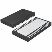
LTC4268IDKD-1#TRPBF Linear Technology, LTC4268IDKD-1#TRPBF Datasheet - Page 11

LTC4268IDKD-1#TRPBF
Manufacturer Part Number
LTC4268IDKD-1#TRPBF
Description
IC PD HIGH POWER W/CNTRL 32-DFN
Manufacturer
Linear Technology
Type
Power over Ethernet Switch (PoE)r
Datasheet
1.LTC4268CDKD-1PBF.pdf
(48 pages)
Specifications of LTC4268IDKD-1#TRPBF
Applications
Remote Peripherals (Industrial Controls, Cameras, Data Access)
Internal Switch(s)
Yes
Operating Temperature
-40°C ~ 85°C
Mounting Type
Surface Mount
Package / Case
32-WFDFN Exposed Pad
Lead Free Status / RoHS Status
Lead free / RoHS Compliant
Available stocks
Company
Part Number
Manufacturer
Quantity
Price
PIN FUNCTIONS
PGDLY (Pin 23): Primary Gate Delay Control. Connect an
external programming resistor (R
synchronous gate turn-off to primary gate turn-on. See
Applications Information for details.
PG (Pin 24): Primary Gate Drive. PG is the gate drive pin
for the primary side MOSFET Switch. Large dynamic cur-
rents fl ow during voltage transitions. See the Applications
Information for details.
NC (Pin 25): No Internal Connection.
V
GND pin to supply power to the fl yback controller through
the internal power MOSFET. V
the input voltage rises above the UVLO turn-on threshold.
The output is then connected to V
rent-limited internal MOSFET switch. Pins 26, 27 and 28
must be electrically tied together.
PWRGD (Pin 29): Active High Power Good Output,
Open-Collector. Signals to the fl yback controller that the
LTC4268-1 MOSFET is on and that the fl yback controller
NEG
(Pins 26, 27, 28): System Negative Rail. Tie to the
NEG
PGDLY
is high impedance until
PORTN
) to set delay from
through a cur-
can start operation. High impedance indicates power is
good. PWRGD is referenced to V
ance during inrush and in the event of a thermal overload.
PWRGD is clamped to 14V above V
PWRGD (Pin 30): Active Low Power Good Output, Open-
Drain. Signals to the DC/DC converter that the LTC4268-1
MOSFET is on and that the converter can start operation.
Low impedance indicates power is good. PWRGD is ref-
erenced to V
tion, classifi cation and in the event of a thermal overload.
PWRGD has no internal clamps.
NC (Pin 31): No Internal Connection.
V
port power return through the input diode bridge.
GND (Pin 33): Ground. This is the negative rail connection
for both signal ground and gate driver grounds. This pin
should be connected to V
to layout. See the Applications Information for details.
PORTP
(Pin 32): Positive Power Input. Tie to the input
PORTN
and is high impedance during detec-
NEG
. Careful attention must be paid
NEG
LTC4268-1
NEG
and is low imped-
.
11
42681fb


