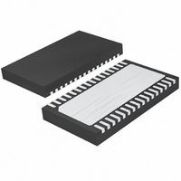
LTC4268IDKD-1#TRPBF Linear Technology, LTC4268IDKD-1#TRPBF Datasheet - Page 27

LTC4268IDKD-1#TRPBF
Manufacturer Part Number
LTC4268IDKD-1#TRPBF
Description
IC PD HIGH POWER W/CNTRL 32-DFN
Manufacturer
Linear Technology
Type
Power over Ethernet Switch (PoE)r
Datasheet
1.LTC4268CDKD-1PBF.pdf
(48 pages)
Specifications of LTC4268IDKD-1#TRPBF
Applications
Remote Peripherals (Industrial Controls, Cameras, Data Access)
Internal Switch(s)
Yes
Operating Temperature
-40°C ~ 85°C
Mounting Type
Surface Mount
Package / Case
32-WFDFN Exposed Pad
Lead Free Status / RoHS Status
Lead free / RoHS Compliant
Available stocks
Company
Part Number
Manufacturer
Quantity
Price
APPLICATIONS INFORMATION
–44V (IEEE 802.3af minimum allowed), the input bridge
will reverse bias and the PD power will be supplied by the
load capacitor. Depending on the size of the load capacitor
and the DC load of the PD, the PD will not draw any power
from the PSE for a period of time. If this period of time
exceeds the IEEE 802.3af 300ms disconnect delay, the
PSE will remove power from the PD. For this reason, it
is necessary to evaluate the load current and capacitance
to ensure that inadvertent shutdown cannot occur. Refer
also to Thermal Protection in this data sheet for further
discussion on load capacitor selection.
MAINTAIN POWER SIGNATURE
In an IEEE 802.3af system, the PSE uses the maintain
power signature (MPS) to determine if a PD continues to
require power. The MPS requires the PD to periodically
draw at least 10mA and also have an AC impedance less
than 26.25k in parallel with 0.05μF . If either the DC current
is less than 10mA or the AC impedance is above 26.25k,
the PSE may disconnect power. The DC current must be
less than 5mA and the AC impedance must be above 2M
to guarantee power will be removed. The PD application
circuits shown in this data sheet present the required AC
impedance necessary to maintain power.
IEEE 802.3at Interoperability
In anticipation of the IEEE 802.3at standard release, the
LTC4268-1 can be combined with a simple external circuit to
be fully interoperable with an IEEE 802.3at-compliant PSE.
For more information, please contact Linear Technology’s
Application Engineering.
PSE
Figure 11. Power Good Interface Example
TO
–54V
V
PORTN
LTC4268-1
PWRGD
V
PORTP
UVLO
42681 F11
V
ACTIVE-HIGH ENABLE
CC
4k
100k
SWITCHING REGULATOR OVERVIEW
The LTC4268-1 includes a current mode converter designed
specifi cally for use in an isolated fl yback topology employing
synchronous rectifi cation. The LTC4268-1 operation is
similar to traditional current mode switchers. The major
difference is that output voltage feedback is derived via
sensing the output voltage through the transformer. This
precludes the need of an optoisolator in isolated designs
greatly improving dynamic response and reliability. The
LTC4268-1 has a unique feedback amplifi er that samples a
transformer winding voltage during the fl yback period and
uses that voltage to control output voltage. The internal
blocks are similar to many current mode controllers.
The differences lie in the feedback amplifi er and load
compensation circuitry. The logic block also contains
circuitry to control the special dynamic requirements of
fl yback control. For more information on the basics of
current mode switcher/controllers and isolated fl yback
converters see Application Note 19.
Feedback Amplifi er—Pseudo DC Theory
For the following discussion refer to the simplifi ed Flyback
Amplifi er diagram(Figure 12A). When the primary side
MOSFET switch MP turns off, its drain voltage rises above
the V
is off and the synchronous secondary MOSFET is on.
During fl yback the voltage on nondriven transformer pins is
determined by the secondary voltage. The amplitude of this
fl yback pulse as seen on the third winding is given as:
R
MS
I
ESR = impedance of secondary circuit capacitor, winding
and traces
N
turns ratio (i.e., N
SEC
DS(ON)
SF
V
= transformer effective secondary-to-fl yback winding
FLBK
= transformer secondary current
PORTP
= on resistance of the synchronous MOSFET
=
rail. Flyback occurs when the primary MOSFET
V
OUT
+I
S
/N
SEC
FLBK
• ESR + R
N
(
)
SF
DS(ON)
LTC4268-1
)
27
42681fb


