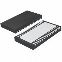
LTC4268IDKD-1#TRPBF Linear Technology, LTC4268IDKD-1#TRPBF Datasheet - Page 18

LTC4268IDKD-1#TRPBF
Manufacturer Part Number
LTC4268IDKD-1#TRPBF
Description
IC PD HIGH POWER W/CNTRL 32-DFN
Manufacturer
Linear Technology
Type
Power over Ethernet Switch (PoE)r
Datasheet
1.LTC4268CDKD-1PBF.pdf
(48 pages)
Specifications of LTC4268IDKD-1#TRPBF
Applications
Remote Peripherals (Industrial Controls, Cameras, Data Access)
Internal Switch(s)
Yes
Operating Temperature
-40°C ~ 85°C
Mounting Type
Surface Mount
Package / Case
32-WFDFN Exposed Pad
Lead Free Status / RoHS Status
Lead free / RoHS Compliant
Available stocks
Company
Part Number
Manufacturer
Quantity
Price
APPLICATIONS INFORMATION
defi ned here is available for system vendors to implement
a unique classifi cation for use in closed systems and is
not defi ned or supported by the IEEE 802.3af. With the
extended classifi cation range available in the LTC4268-1, it
is possible for system designers to defi ne multiple classes
using load currents between 40mA and 75mA.
During classifi cation, the PSE presents a fi xed voltage
between –15.5V and –20.5V to the PD (Figure 6a). With the
input voltage in this range, the LTC4268-1 asserts a load
current from the V
The magnitude of the load current is set with the selection
of the R
each class is shown in Table 2.
Table 2. Summary of IEEE 802.3af Power Classifi cations and
LTC4268-1 R
A substantial amount of power is dissipated in the
LTC4268-1 during classification. The IEEE 802.3af
specifi cation limits the classifi cation time to 75ms in order
avoid excessive heating. The LTC4268-1 is designed to
handle the power dissipation during the probe period.
If the PSE probing exceeds 75ms, the LTC4268-1 may
overheat. In this situation, the thermal protection circuit
will engage and disable the classifi cation current source,
protecting the LTC4268-1 from damage. When the die
cools, classifi cation is automatically resumed.
Classifi cation presents a challenging stability problem
for the PSE due to the wide range of loads possible. The
LTC4268-1 has been designed to avoid PSE interoperability
problems by maintaining a positive I-V slope throughout
LTC4268-1
18
CLASS
0
1
2
3
4
5
Undefi ned by IEEE. See Apps
CLASS
Reserved by IEEE. See Apps
Optional
Optional
Optional
USAGE
Default
CLASS
resistor. The resistor value associated with
Resistor Selection
POWER LEVELS
AT INPUT OF PD
0.44 to 12.95
6.49 to 12.95
PORTP
0.44 to 3.84
3.84 to 6.49
MAXIMUM
(W)
pin through the R
CLASSIFICATION
LOAD CURRENT
NOMINAL
(mA)
10.5
18.5
<5
28
40
56
CLASS
LTC4268-1
RESISTOR
RCLASS
(Ω, 1%)
resistor.
Open
69.8
45.3
30.9
22.1
124
–15.5V TO –20.5V
the signature and classifi cation ranges up to UVLO turn
on as shown in Figure 6b. The positive I-V slope avoids
areas of negative resistance and helps prevent the PSE
from power cycling or getting “stuck” during signature
or classifi cation probing. In the event a PSE overshoots
beyond the classifi cation voltage range, the available load
current aids in returning the PD back into the classifi cation
voltage range. (The PD input may otherwise be “trapped”
by a reverse-biased diode bridge and the voltage held by
the 0.1μF capacitor.) By gently ramping the classifi cation
current on and maintaining a positive I-V slope until UVLO
turn-on, the LTC4268-1 provides a well behaved load,
assuring interoperability with any PSE.
PROBING
VOLTAGE
SOURCE
PSE CURRENT MONITOR
PSE
Figure 6a. PSE Probing PD During Classifi cation
Figure 6b. LTC4268-1 Positive I-V Slope
0
PSE
V
–10
CURRENT PATH
V
PORT
R
–20
CLASS
(V)
LTC4268-1
R
V
PORTN
CLASS
–30
PD
42681 F06b
V PORTP
42681 F06a
–40
CONSTANT
LOAD
CURRENT
INTERNAL
TO LTC4268-1
42681fb


