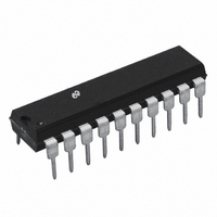
LMD18400N/NOPB National Semiconductor, LMD18400N/NOPB Datasheet - Page 10

LMD18400N/NOPB
Manufacturer Part Number
LMD18400N/NOPB
Description
IC DRIVER QUAD HI SIDE 20-DIP
Manufacturer
National Semiconductor
Datasheet
1.LMD18400NNOPB.pdf
(19 pages)
Specifications of LMD18400N/NOPB
Configuration
High-Side
Input Type
Non-Inverting
Delay Time
5µs
Current - Peak
3A
Number Of Configurations
4
Number Of Outputs
4
Voltage - Supply
7 V ~ 28 V
Operating Temperature
-25°C ~ 85°C
Mounting Type
Through Hole
Package / Case
20-DIP (0.300", 7.62mm)
Supply Voltage Min
7V
Supply Voltage Max
60V
No. Of Outputs
4
Output Voltage
5.5V
Output Current
3.75A
Driver Case Style
DIP
Msl
MSL 1 - Unlimited
Device Type
High Side
Rohs Compliant
Yes
Lead Free Status / RoHS Status
Lead free / RoHS Compliant
High Side Voltage - Max (bootstrap)
-
Other names
*LMD18400N
*LMD18400N/NOPB
LMD18400N
*LMD18400N/NOPB
LMD18400N
Available stocks
Company
Part Number
Manufacturer
Quantity
Price
Company:
Part Number:
LMD18400N/NOPB
Manufacturer:
National Semiconductor
Quantity:
135
www.national.com
Applications Information
When the output inductance produces a negative voltage,
the gate of the DMOS transistor is clamped at 0V. At −3.5V,
the source of the power device is less than the gate by
enough to cause the switch to turn ON again. During this
negative transient condition the power limiting circuitry to
protect the switch is disabled due to the gate being held at
0V. The maximum current during this clamping interval,
which is equal to the steady state ON current through the
inductor, should be kept less than 1A. Another concern
during this interval has to do with the size of an inductive
load and the amount of time required to de-energize it. With
larger inductors it may be possible for the additional power
dissipation to cause the die temperature to exceed the ther-
mal shutdown limit. If this occurs all of the other switches will
turn OFF momentarily (see section on Thermal Manage-
ment).
Power Limiting
The LMD18400 utilizes a true instantaneous power limit
circuit rather than simple current limiting to protect each
switch. This provides a higher transient current capability
while still maintaining a safe power dissipation level. The
power dissipation in each switch (the product of the Drain-
to-Source voltage and the output current, V
continually monitored and limited to 15W by varying the gate
voltage and therefore the ON resistance of the switch. Basi-
cally the ON resistance will be as low as possible until 15W
is being dissipated. To maintain 15W, the ON resistance
increases to reduce the load current. This results in a de-
crease of the output voltage. For resistive loads, the output
voltage when in power limit will be:
This provides a maximum transient current, and drain-to-
source voltage characteristic as shown in Figure 5.
FIGURE 4. Turn-OFF Conditions with an Inductive
Load
(Continued)
ds
01102613
x I
OUT
) is
10
The steady state current to the load is limited by the package
power dissipation, ambient temperature and the ON resis-
tance of the switch which has a positive temperature coeffi-
cient as shown in the Typical Performance Characteristics.
This dynamic current limiting of the switches is beneficial
when driving lamp and large capacitive loads. Lamps require
a large inrush current, on the order of 10 times the normal
operating current, when first switched on with a cold fila-
ment. The LMD18400 will limit this initial current to the level
where 15W is dissipated in the switch. As the filament warms
up the voltage across the lamp increases thereby decreas-
ing the voltage across the switch which permits more current
to fully light the lamp. With limited inrush current the lifetime
of a lamp load is increased significantly. Figure 6 illustrates
the soft turn-on of a lamp load.
The same principle of increasing output current as the volt-
age across the load increases allows large capacitive loads
to be charged more quickly by an LMD18400 driver than as
opposed to a driver with a fixed 1A current limit protection
scheme. Figure 7 shows the output response while driving a
large capacitive load.
FIGURE 5. Maximum Output Current with
FIGURE 6. Soft Turn-On of a Lamp Load
Instantaneous Power Limiting
Driving a Lamp
01102615
01102614


