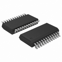
ADT7476ARQZ ON Semiconductor, ADT7476ARQZ Datasheet - Page 20

ADT7476ARQZ
Manufacturer Part Number
ADT7476ARQZ
Description
IC REMOTE THERMAL CTRLR 24QSOP
Manufacturer
ON Semiconductor
Series
dBCool®r
Datasheet
1.ADT7476ARQZ-REEL.pdf
(67 pages)
Specifications of ADT7476ARQZ
Function
Fan Control, Temp Monitor
Topology
ADC, Comparator, Fan Speed Counter, Multiplexer, Register Bank
Sensor Type
External & Internal
Sensing Temperature
-40°C ~ 125°C, External Sensor
Output Type
SMBus™
Output Alarm
No
Output Fan
Yes
Voltage - Supply
3 V ~ 3.6 V
Operating Temperature
-40°C ~ 125°C
Mounting Type
Surface Mount
Package / Case
24-QSOP
Full Temp Accuracy
+/- 0.5 C
Digital Output - Bus Interface
Serial (3-Wire, 4-Wire)
Maximum Operating Temperature
+ 125 C
Minimum Operating Temperature
- 40 C
Lead Free Status / RoHS Status
Lead free / RoHS Compliant
Available stocks
Company
Part Number
Manufacturer
Quantity
Price
Part Number:
ADT7476ARQZ
Manufacturer:
ADI/亚德诺
Quantity:
20 000
Part Number:
ADT7476ARQZ-REEL
Manufacturer:
ON/安森美
Quantity:
20 000
Configuration Register 2 (0x73)
[4] = 1, averaging off.
[6] = 1, single−channel convert mode.
TACH1 Minimum High Byte (0x55)
[7:5] selects ADC channel for single−channel convert mode.
Overtemperature Events
channels can be detected and dealt with automatically in
automatic fan speed control mode. Register 0x6A to
Register 0x6C are the THERM temperature limits. When a
temperature exceeds its THERM temperature limit, all
PWM outputs run at the maximum PWM duty cycle
(Register 0x38, Register 0x39, and Register 0x3A).
This effectively runs the fans at the fastest allowed speed.
below THERM minus hysteresis. This can be disabled by
setting Bit 2, the boost bit, in Configuration Register 3
(0x78). The hysteresis value for the THERM temperature
limit is the value programmed into the hysteresis registers
(0x6D and 0x6E). The default hysteresis value is 4°C.
using Bits [7:5] of Configuration Register 5 (0x7C).
THERM can also be disabled by:
•
•
Table 10. Programming Single−Channel ADC Mode
for Temperatures
Bits [7:5], Register 0x55
Overtemperature events on any of the temperature
The fans run at this speed until the temperature drops
THERM can be disabled on specific temperature channels
THERM LIMIT
TEMPERATURE
FANS
Writing −64°C to the appropriate THERM temperature
limit in Offset 64 mode.
Writing −128°C to the appropriate THERM
temperature limit in twos complement mode.
Figure 28. THERM Temperature Limit Operation
101
110
111
100%
Channel Selected
Remote 1 Temperature
Local Temperature
Remote 2 Temperature
HYSTERESIS (°C)
http://onsemi.com
20
Limits, Status Registers, and Interrupts
Limit Values
ADT7476 are high and low limits. These can form the basis of
system status monitoring; a status bit can be set for any
out−of−limit condition and is detected by polling the device.
Alternatively, SMBALERT interrupts can be generated to flag
out−of−limit conditions to a processor or microcontroller.
8−Bit Limits
Voltage Limit Registers
Register 0x44, 2.5 V Low Limit = 0x00 default
Register 0x45, 2.5 V High Limit = 0xFF default
Register 0x46, V
Register 0x47, V
Register 0x48, V
Register 0x49, V
Register 0x4A, 5.0 V Low Limit = 0x00 default
Register 0x4B, 5.0 V High Limit = 0xFF default
Register 0x4C, 12 V Low Limit = 0x00 default
Register 0x4D, 12 V High Limit = 0xFF default
Temperature Limit Registers
Register 0x4E, Remote 1 Temperature Low Limit = 0x81 default
Register 0x4F, Remote 1 Temperature High Limit = 0x7F default
Register 0x6A, Remote 1 THERM Limit = 0x64 default
Register 0x50, Local Temperature Low Limit = 0x81 default
Register 0x51, Local Temperature High Limit = 0x7F default
Register 0x6B, Local THERM Limit = 0x64 default
Register 0x52, Remote 2 Temperature Low Limit = 0x81 default
Register 0x53, Remote 2 Temperature High Limit = 0x7F default
Register 0x6C, Remote 2 THERM Limit = 0x64 default
THERM Timer Limit Register
Register 0x7A, THERM Timer Limit = 0x00 default.
16−Bit Limits
TACH limits are also 16 bits, consisting of a high byte and
low byte. Because fans running under speed or stalled are
normally the only conditions of interest, only high limits
exist for fan TACHs. Because the fan TACH period is
actually being measured, exceeding the limit indicates a
slow or stalled fan.
Associated with each measurement channel on the
The following is a list of 8−bit limits on the ADT7476.
The fan TACH measurements are 16−bit results. The fan
CCP
CCP
CC
CC
High Limit = 0xFF default
Low Limit = 0x00 default
Low Limit = 0x00 default
High Limit = 0xFF default


