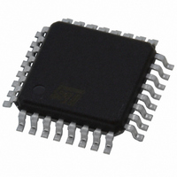
L5994 STMicroelectronics, L5994 Datasheet - Page 19

L5994
Manufacturer Part Number
L5994
Description
IC CTRLR PS ADJ TRPL-OUT 32-TQFP
Manufacturer
STMicroelectronics
Datasheet
1.L5994.pdf
(26 pages)
Specifications of L5994
Pwm Type
Current Mode
Number Of Outputs
3
Frequency - Max
345kHz
Duty Cycle
96%
Voltage - Supply
4.75 V ~ 25 V
Buck
Yes
Boost
No
Flyback
Yes
Inverting
No
Doubler
No
Divider
No
Cuk
No
Isolated
No
Operating Temperature
-40°C ~ 140°C
Package / Case
32-TQFP, 32-VQFP
Frequency-max
345kHz
Lead Free Status / RoHS Status
Lead free / RoHS Compliant
Available stocks
Company
Part Number
Manufacturer
Quantity
Price
Transformer Catch Diode (L5994A only)
The diode which steers the current generated by the secondary winding of the +5.1V transformer should be a
fast-recovery one, with a breakdown voltage greater than:
with a certain safety margin. The diode has to withstand a pulsed current whose peak value is approximately:
while its RMS value is given by:
The DC value is obviously I
Transformer Filter Capacitors
The most stringent requirement on the input filter capacitor (connected between V13IN and ground) is its RMS
ripple current rating, which should be at least:
The working voltage should be higher than the voltage generated when the regulator is lightly loaded. Also for
this part the use of high quality electrolytic or OS-CON capacitors is advised.
Layout and Grounding
The electrical design is only the first step in the development of a switching converter. Since currents ranging
from mA to some A, both DC and switched, live together on the same circuitboard, the PCB layout is vital for a
correct operation of the circuit but is not an easy task.
A proper layout process generally includes careful component placing, proper grounding, correct traces routing,
and appropriate trace widths. Fortunately, since low voltages are involved in this kind of applications, isolation
requirements are of no concern.
Referring to literature for a detailed analysis of this matter, only few important points will be here reminded.
1) All current returns (signal ground, power ground, etc.) should be mutually isolated and should be con-
2) Noise coupling between adjacent circuitry can be reduced minimizing the area of the loop where current
3) Magnetic field radiation (and stray inductance) can be reduced by keeping all traces which carry
4) The Kelvin-connected traces of current sense should be kept short and close together.
5) For high current paths, the traces could be doubled on the other side of the PCB whenever possible: this
6) In general, traces carrying signal currents should run far from traces carrying pulsed currents or with
nected only at a single ground point. Ground planes may be extremely useful both to arrange properly
current returns and to minimize radiation (see next 2 points), even though they cannot solve every prob-
lem
flows. This is particularly important where there are high pulsed currents, that is the circuit including the
input filter capacitor, the power switch, the synchronous rectifier and the output capacitor. The next pri-
ority should be given to the gate drive circuits.
switched currents as short as possible.
will reduce both the resistance and the inductance of the wiring.
quickly swinging voltages. From this viewpoint, particular care should be taken of the high impedance
paths (feedback input, current sense traces...). It could be a good idea to route signal traces on one PCB
OUT12
V
.
RR
I
13RM S
I
=
13AC
I
13PK
V
INLIN
=
–
=
I
I
OUT12
OUT12
I
OUT12
–
5.1
+
---------------------------------
V
---------------------------------
V
INM IN
---------------------------------
V
V
INM IN
INM IN
INMIN
V
V
5.1
INM IN
INM AX
–
–
5.1
–
5.1
5.1
–
5.1
L5994 - L5994A
19/26


