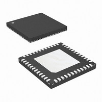
ISL6307CRZ Intersil, ISL6307CRZ Datasheet - Page 24

ISL6307CRZ
Manufacturer Part Number
ISL6307CRZ
Description
IC CTRLR PWM 6-PHASE 48-QFN
Manufacturer
Intersil
Datasheet
1.ISL6307CRZ.pdf
(34 pages)
Specifications of ISL6307CRZ
Pwm Type
Voltage Mode
Number Of Outputs
6
Frequency - Max
275kHz
Duty Cycle
66.7%
Voltage - Supply
4.75 V ~ 5.25 V
Buck
Yes
Boost
No
Flyback
No
Inverting
No
Doubler
No
Divider
No
Cuk
No
Isolated
No
Operating Temperature
0°C ~ 70°C
Package / Case
48-VQFN
Frequency-max
275kHz
Lead Free Status / RoHS Status
Lead free / RoHS Compliant
Available stocks
Company
Part Number
Manufacturer
Quantity
Price
Part Number:
ISL6307CRZ
Manufacturer:
INTERSIL
Quantity:
20 000
Part Number:
ISL6307CRZ-T
Manufacturer:
INTERSIL
Quantity:
20 000
voltage on EN_PWR, EN_VTT or VCC below the POR-
falling threshold will reset the controller. Cycling the VID
codes will not reset the controller.
Overcurrent Protection
ISL6307 has two levels of overcurrent protection. Each
phase is protected from a sustained overcurrent condition on
a delayed basis, while the combined phase currents are
protected on an instantaneous basis.
In instantaneous protection mode, the ISL6307 takes
advantage of the proportionality between the load current
and the average current, I
condition. See the Channel-Current Balance section for
more detail on how the average current is measured. The
average current is continually compared with a constant
100µA reference current as shown in Figure 12. Once the
average current exceeds the reference current, a
comparator triggers the converter to shutdown.
In individual overcurrent protection mode, the ISL6307
continuously compares the current of each channel with the
same 100µA reference current. If any channel current
exceeds the reference current continuously for eight
consecutive cycles, the comparator triggers the converter to
shutdown.
The overcurrent protection level for the above two OCP
modes can be adjusted by changing the value of current
sensing resistors. In addition, ISL6307 can also adjust the
average OCP threshold level by adjusting the value of the
resistor from IOUT to GND. This provides additional safety
for the voltage regulator.
The following equation can be used to calculate the value of
the resistor R
OCP2
R
IOUT
.
=
-------------------------------
I
AVG OCP2
IOUT
,
2
based on the desired OCP level I
AVG
24
, to detect an overcurrent
AVG,
(EQ. 17)
ISL6307
At the beginning of overcurrent shutdown, the controller
places all PWM signals in a high-impedance state within
20ns commanding the Intersil MOSFET driver ICs to turn off
both upper and lower MOSFETs. The system remains in this
state a period of 4096 switching cycles. If the controller is still
enabled at the end of this wait period, it will attempt a soft-
start. If the fault remains, the trip-retry cycles will continue
indefinitely (as shown in Figure 13) until either controller is
disabled or the fault is cleared. Note that the energy
delivered during trip-retry cycling is much less than during
full-load operation, so there, there is no thermal hazard
during this kind of operation.
Current Sense Output
The ISL6307 has 2 current sense output pins IDROOP and
IOUT; They are identical. In typical application, IDROOP pin
is connected to FB pin for the application where load line is
required. IOUT pin was designed for load current
measurement. As shown in typical application schematics
on pages 4 to 7, load current information can be obtained by
measuring the voltage at IOUT pin with a resistor connecting
IOUT PIN to ground. When the programmable temperature
compensation function of ISL6307 is properly used, the
output current at IOUT pin is proportional to load current as
shown in Figure 14.
FIGURE 13. OVERCURRENT BEHAVIOR IN HICCUP MODE.
0A
0V
OUTPUT CURRENT, 50A/DIV
F
OUTPUT VOLTAGE,
500mV/DIV
SW
= 500kHz
2ms/DIV
March 9, 2006
FN9224.0


