L6756D STMicroelectronics, L6756D Datasheet - Page 8

L6756D
Manufacturer Part Number
L6756D
Description
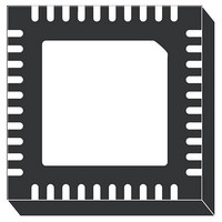
IC CTLR 2/3/4PH BUCK 40-VFQFPN
Manufacturer
STMicroelectronics
Datasheet
1.L6756DTR.pdf
(36 pages)
Specifications of L6756D
Applications
Controller, Intel VR10, VR11, VR11.1
Voltage - Input
12V
Number Of Outputs
4
Voltage - Output
0.3 ~ 1.6 V
Operating Temperature
0°C ~ 70°C
Mounting Type
Surface Mount
Package / Case
40-VFQFN, 40-VFQFPN
Output Voltage
3 V
Input Voltage
- 0.3 V to + 15 V
Switching Frequency
185 KHz to 215 KHz
Operating Temperature Range
- 40 C to + 150 C
Mounting Style
SMD/SMT
Lead Free Status / RoHS Status
Lead free / RoHS Compliant
Available stocks
Company
Part Number
Manufacturer
Quantity
Price
Pins description and connection diagrams
2
2.1
8/36
Pins description and connection diagrams
Figure 5.
Pin descriptions
Table 2.
2 to 9
Pin#
10
11
1
PSI# / VR10
VID0 to
Name
VID7
EN
SS
Pins connection (top view)
Pin description
VR enable. Internally pulled-up by 10 μA to 3.3 V.
Pull-low to disable the device, set free or pull up above turn-on threshold to
enable the controller.
Voltage IDentification pins.
3.3 V compatible, they allow programming output voltage as specified in
Table 6
According to the status of PSI_A, the functionality of this pin changes as
below:
PSI#: Power state indicator input. Connect to the PSI# pin on the CPU to
manage low-power state. When asserted (pulled low), the controller will act as
programmed on the PSI_A pin.
VR10: It allows selecting between VR10 (short to SGND, See
(floating, See
By connecting a resistor R
soft-start time T
18.52 [µs / kΩ]. Connect 27 kΩ resistor to program T2 = 500 µs. The same
slope implemented to reach V
reference moves from V
fixed 1.24 V.
and
Table 7
Table
SS
will proportionally change with a gain of
7) DACs.
according to VR10/1 pin status.
BOOT
SS
to GND, it allows programming the soft-start time.
to the programmed VID code. The pin is kept to a
BOOT
Function
has to be considered also when the
Table
6) or VR11
L6756D


