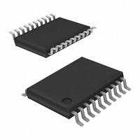
EL7581IREZ Intersil, EL7581IREZ Datasheet - Page 11

EL7581IREZ
Manufacturer Part Number
EL7581IREZ
Description
IC CONV DC/DC 3-CHAN 20-HTSSOP
Manufacturer
Intersil
Datasheet
1.EL7581IREZ.pdf
(17 pages)
Specifications of EL7581IREZ
Applications
Converter, TFT, LCD
Voltage - Input
2.7 ~ 14 V
Number Of Outputs
2
Voltage - Output
5 ~ 17 V
Operating Temperature
-40°C ~ 85°C
Mounting Type
Surface Mount
Package / Case
20-TSSOP Exposed Pad, 20-eTSSOP, 20-HTSSOP
Lead Free Status / RoHS Status
Lead free / RoHS Compliant
Available stocks
Company
Part Number
Manufacturer
Quantity
Price
Part Number:
EL7581IREZ
Manufacturer:
INTERSIL
Quantity:
20 000
Part Number:
EL7581IREZ-T13
Manufacturer:
INTERSIL
Quantity:
20 000
Applications Information
The EL7581 is high efficiency multiple output power solution
designed specifically for thin-film transistor (TFT) liquid
crystal display (LCD) applications. The device contains one
high current boost converter and two low power charge
pumps (V
The boost converter contains an integrated N-channel
MOSFET to minimize the number of external components.
The converter output voltage can be set from 5V to 18V with
external resistors. The V
independently regulated to positive and negative voltages
using external resistors. Output voltages as high as 40V can
be achieved with additional capacitors and diodes.
Boost Converter
The boost converter operates in constant frequency pulse-
width-modulation (PWM) mode. Quiescent current for the
EL7581 is only 5mA when enabled, and since only the low
side MOSFET is used, switch drive current is minimized.
90% efficiency is achieved in most common application
operating conditions.
A functional block diagram with typical circuit configuration is
shown on the previous page. Regulation is performed by the
PWM comparator which regulates the output voltage by
comparing a divided output voltage with an internal
reference voltage. The PWM comparator outputs its result to
the PWM logic. The PWM logic switches the MOSFET on
and off through the gate drive circuit. Its switching frequency
is external adjustable with a resistor from timing control pin
(R
1.2MHz operating frequency range.
Start-Up
After V
MOSFET is controlled by the start-up oscillator, which
generates fixed duty-ratio of 0.5 - 0.7 at a frequency of
several hundred kilohertz. This will boost the output voltage,
providing the initial output current load is not too great
(<250mA).
When V
takes over the control. The duty ratio will be decided by the
multiple-input direct summing comparator, Max_Duty signal
(about 90% duty-ratio), and the Current Limit Comparator,
whichever is the smallest.
The soft-start is provided by the current limit comparator. As
the internal 12µA current source charges the external soft-
start capacitor, the peak MOSFET current is limited by the
voltage on the capacitor. This in turn controls the rising rate
of output voltage.
The regulator goes through the start-up sequence as well
after the ENBN signal is pulled to HI.
OSC
) to ground. The boost converter has 200kHz to
DDB
DDB
ON
reaches a threshold of about 2V, the power
reaches about 3.7V, the PWM comparator
and V
OFF
).
ON
and V
11
OFF
charge pumps are
EL7581
Steady-State Operation
When the output reaches the preset voltage, the regulator
operates at steady state. Depending on the input/output
condition and component, the inductor operates at either
continuous-conduction mode or discontinuous-conduction
mode.
In the continuous-conduction mode, the inductor current is a
triangular waveform and LX voltage a pulse waveform. In the
discontinuous-conduction mode, the inductor current is
completely ‘dried-out’ before the MOSFET is turned on
again. The input voltage source, the inductor, and the
MOSFET and output diode parasitic capacitors forms a
resonant circuit. Oscillation will occur in this period. This
oscillation is normal and will not affect the regulation.
At very low load, the MOSFET will skip pulse sometimes.
This is normal.
Current Limit
The MOSFET current limit is nominal I
restricts the maximum output current I
following formula:
where:
• ∆I
• D is the MOSFET turn-on radio and is decided by:
• F
The following table gives typical values:
(Margins are considered in deriving I
3%, 20%, 10%, and 20% on V
respectively.)
I
∆I
D
OMAX
decided by:
L
=
V
S
TABLE 1. MAXIMUM CONTINUOUS OUTPUT CURRENT
IN
L
=
3.3
3.3
3.3
3.3
V
----------------------- -
12
12
5
5
5
is the switching frequency.
is the inductor peak-to-peak current ripple and is
O
V
---------
(V)
=
L
V
IN
- V
O
×
I
LMT
IN
------ -
F
D
S
V
–
O
∆L
------ -
12
15
12
15
15
18
5
9
9
2
(V)
×
V
---------
V
IN
O
L (µH)
10
10
10
10
10
10
10
10
10
IN
, V
O
OMAX
, L, F
OMAX
LMT
F
S
1000
1000
1000
1000
1000
1000
1000
1000
1000
(kHz)
S
. They are 10%,
= 2.75A. This
, and I
based on the
I
OMAX
LMT
1200
1300
1100
660
490
390
980
720
570
,
(mA)


