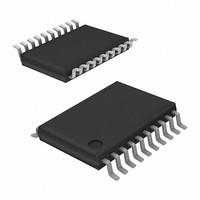
EL7581IREZ Intersil, EL7581IREZ Datasheet - Page 2

EL7581IREZ
Manufacturer Part Number
EL7581IREZ
Description
IC CONV DC/DC 3-CHAN 20-HTSSOP
Manufacturer
Intersil
Datasheet
1.EL7581IREZ.pdf
(17 pages)
Specifications of EL7581IREZ
Applications
Converter, TFT, LCD
Voltage - Input
2.7 ~ 14 V
Number Of Outputs
2
Voltage - Output
5 ~ 17 V
Operating Temperature
-40°C ~ 85°C
Mounting Type
Surface Mount
Package / Case
20-TSSOP Exposed Pad, 20-eTSSOP, 20-HTSSOP
Lead Free Status / RoHS Status
Lead free / RoHS Compliant
Available stocks
Company
Part Number
Manufacturer
Quantity
Price
Part Number:
EL7581IREZ
Manufacturer:
INTERSIL
Quantity:
20 000
Part Number:
EL7581IREZ-T13
Manufacturer:
INTERSIL
Quantity:
20 000
Absolute Maximum Ratings
V
V
LX Voltage . . . . . . . . . . . . . . . . . . . . . . . . . . . . . . . . . . . . . . . . . .18V
Maximum Continuous Output Current . . . . . . . . . . . . . . . . . . . . . .1A
CAUTION: Stresses above those listed in “Absolute Maximum Ratings” may cause permanent damage to the device. This is a stress only rating and operation of the
device at these or any other conditions above those indicated in the operational sections of this specification is not implied.
IMPORTANT NOTE: All parameters having Min/Max specifications are guaranteed. Typ values are for information purposes only. Unless otherwise noted, all tests are
at the specified temperature and are pulsed tests, therefore: T
Electrical Specifications
DC/DC BOOST CONVERTER
IQ1_B
IQ2_B
V(FBB)
V
V
I(FBB)
V
D
I(LX)
R
I
V
∆V
∆V
F
F
POSITIVE REGULATED CHARGE PUMP (V
Most positive V
configuration (doubler or tripler)
V
IQ1(V
IQ2(V
V(FBP)
I(FBP)
I(DRVP)
ILR_V
F
IN
DDB
LEAK-SWITCH
PARAMETER
OSC-RANGE
OSC1
PUMP
REF
ROSC
DDB
MAX
DS-ON
BOOST
DDP
BOOST
BOOST
Input Voltage . . . . . . . . . . . . . . . . . . . . . . . . . . . . . . . . . . . .14V
, V
MAX
DDP
DDP
ON
DDP
/∆V
/∆I
)
)
, V
O1
IN
DDN
ON
Quiescent Current - Shut-down
Quiescent Current - Switching
Feedback Voltage
Reference Voltage
Oscillator Set Voltage
Feedback Input Bias Current
Boost Converter Supply Range
Maximum Duty Cycle
Peak Internal FET Current
Switch On Resistance
Switch Leakage Current
Output Range
Line Regulation
Load Regulation
Frequency Range
Switching Frequency
Supply Input for Positive Charge Pump
Quiescent Current - Shut-down
Quiescent Current - Switching
Feedback Reference Voltage
Feedback Input Bias Current
RMS DRVP Output Current
Load Regulation
Charge Pump Frequency
output depends on the magnitude of the V
. . . . . . . . . . . . . . . . . . . . . . . . . . . . . . . . . . .18V
DESCRIPTION
2
V
IN
(T
A
= 3.3V, V
= 25°C)
ON
BOOST
)
J
= T
= 12V, R
C
= T
ENBN = ENP = 0V
ENBN = V
at V
I(LX) total
V
2.7V < V
50mA < I
R
R
Usually connected to V
ENP = 0V
ENBN = ENP = V
V
V
5mA < I
Frequency set by R
DDP
BOOST
DDP
DDP
OSC
OSC
A
OSC
BOOST
EL7581
input voltage (normally connected to V
= 12V
= 6V
range = 240kΩ to 60kΩ
= 100kΩ
L
IN
= 100kΩ, T
> V
O1
< 15mA
DDB
< 13.2V, V
= 10V, I(LX) total = 500mA
< 300mA
IN
CONDITIONS
+ V
Storage Temperature . . . . . . . . . . . . . . . . . . . . . . . .-65°C to +150°C
Die Junction Temperature . . . . . . . . . . . . . . . . . . . . . . . . . . . . 125°C
Power Dissipation . . . . . . . . . . . . . . . . . . . . . . . . . . . . . See Curves
Operating Ambient Temperature . . . . . . . . . . . . . . . .-40°C to +85°C
DDB
DIODE
OSC
A
= 25°C Unless Otherwise Specified.
BOOST
BOOST
- see boost section
= 15V
output
BOOST
1.275
1.260
1.260
1.245
MIN
-0.5
200
620
2.7
85
15
5
5
) and the external component
0.5*F
1.300
1.310
1.325
1.310
TYP
2.75
0.15
11.5
0.03
680
0.8
4.8
0.1
0.1
0.5
2.3
0.1
92
60
OSC
1.325
1.360
1.390
1.375
MAX
1000
750
0.5
10
17
17
17
20
8
2
5
%/mA
UNIT
kHz
kHz
mA
mA
mA
mA
µA
µA
µA
µA
µA
%
%
%
V
V
V
Ω
V
V
A
V
V


