ISL6539IAZ-T Intersil, ISL6539IAZ-T Datasheet - Page 12
ISL6539IAZ-T
Manufacturer Part Number
ISL6539IAZ-T
Description
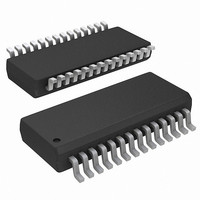
IC CTRLR DDR DRAM, SDRAM 28QSOP
Manufacturer
Intersil
Datasheet
1.ISL6539CAZ.pdf
(20 pages)
Specifications of ISL6539IAZ-T
Applications
Controller, DDR DRAM, SDRAM
Voltage - Input
3.3 ~ 18 V
Number Of Outputs
2
Voltage - Output
0.9 ~ 5.5 V
Operating Temperature
-40°C ~ 85°C
Mounting Type
Surface Mount
Package / Case
28-QSOP
Lead Free Status / RoHS Status
Lead free / RoHS Compliant


resistor R
system loop gain can be accurately analyzed and modified
by the system designers based on the applications
requirements.
Gate Control Logic
The gate control logic translates generated PWM signals
into gate drive signals providing necessary amplification,
level shift, and shoot-through protection. It bears some
functions that help to optimize the IC performance over a
wide range of the operational conditions. As MOSFET
switching time can vary dramatically from type to type, and
with the input voltage, the gate control logic provides
adaptive dead time by monitoring real gate waveforms of
both the upper and the lower MOSFETs.
Dual-Step Conversion
The ISL6539 dual channel controller can be used either in
power systems with a single-stage power conversion or in
systems where some intermediate voltages are initially
established. The choice of the approach may be dictated by
the overall system design criteria, or the approach may be a
matter of voltages available to the system designer.
When the output voltage is regulated from low voltage such
as 5V, the feed-forward ramp may become too shallow,
creating the possibility of duty-factor jitter; this is particularly
relevant in a noisy environment. Noise susceptibility, when
operating from low level regulated power sources, can be
improved by connecting the VIN pin to ground, by which the
feed-forward ramp generator will be internally reconnected
from the VIN pin to the VCC pin, and the ramp slew rate will
be doubled.
FIGURE 9. THE BODE PLOT OF THE LC FILTER,
-10
-20
-30
-40
-50
-60
60
50
40
30
20
10
0
100
CS
VO/VC
, output LC filter, and feedback network, the
COMPENSATOR, CONTROL TO OUTPUT
VOLTAGE TRANSFER FUNCTION, AND SYSTEM
LOOP GAIN
1•10
3
LC FILTER
FREQUENCY (Hz)
12
1•10
4
COMPENSATOR
1•10
LOOP GAIN
5
1•10
6
ISL6539
Voltage Monitor and Protections
The converter output is monitored and protected against
extreme overload, short circuit, overvoltage, and
undervoltage conditions. A sustained overload on the output
sets the PGOOD low and latches off the offending channel of
the chip. The controller operation can be restored by cycling
the VCC voltage or toggling both enable (EN) pins to low to
clear the latch.
Power Good
In the soft-start process, the PGOOD is established after the
soft pin voltage is at 1.5V. In normal operation, the PGOOD
window is 100mV below the 0.9V and 135mV higher than
0.9V. The VSEN pin has to stay within this window for
PGOOD to be high. Since the VSEN pin is used for both
feedback and monitoring purposes, the output voltage
deviation can be coupled directly to the VSEN pin by the
capacitor in parallel with the voltage divider as shown in
Figure 6. In order to prevent false PGOOD drop, capacitors
need to parallel at the output to confine the voltage deviation
with severe load step transient. The PGOOD comparator has
a built-in 3µs filter. PGOOD is an open drain output.
Overcurrent Protection
In dual switcher application, both PWM controllers use the
lower MOSFETs on-resistance r
current for protection against shorted outputs. The sensed
current from the ISEN pin is compared with a current set by
a resistor connected from the OCSET pin to ground:
where I
R
the ISEN pin. The 8µA is the offset current added on top of
the sensed current from the ISEN pin for internal circuit
biasing.
If the lower MOSFET current exceeds the overcurrent
threshold, a pulse skipping circuit is activated. The upper
MOSFET will not be turned on as long as the sensed current
is higher than the threshold value, limiting the current
supplied by the DC voltage source. The current in the lower
MOSFET will be continuously monitored until it is lower than
the OC threshold value, then the following UGATE pulse will
be released and normal current sample resumes. This kind
of operation remains for 8 clock cycles after the overcurrent
comparator was tripped for the first time. If after the first 8
clock cycles the current exceeds the overcurrent threshold
again, in a time interval of another 8 clock cycles, the
overcurrent protection latches and disables the offending
channel. If the overcurrent condition goes away during the
first 8 clock cycles, normal operation is restored and the
overcurrent circuit resets itself at the end of 16 clock cycles
(See Figure 10).
R
CS
SET
is the value of the current sense resistor connected to
=
OC
-------------------------------------------------------- -
I
--------------------------------------
OC
R
CS
is a desired overcurrent protection threshold and
•
r
+
DS ON
10.3V
140Ω
(
)
+
8μA
DS(ON),
to monitor the
April 29, 2010
(EQ. 14)
FN9144.6
Related parts for ISL6539IAZ-T
Image
Part Number
Description
Manufacturer
Datasheet
Request
R

Part Number:
Description:
Wide Input Range Dual PWM Controller with DDR Option
Manufacturer:
Intersil Corporation
Datasheet:

Part Number:
Description:
ISL6539 EVAL BOARD 2 - SSOP - Dual Switching Regulator
Manufacturer:
Intersil
Part Number:
Description:
Intersil Corporation [CMOS Serial Controller Interface]
Manufacturer:
Intersil Corporation
Datasheet:
Part Number:
Description:
Manufacturer:
Intersil Corporation
Datasheet:
Part Number:
Description:
357-036-542-201 CARDEDGE 36POS DL .156 BLK LOPRO
Manufacturer:
Intersil Corporation
Datasheet:
Part Number:
Description:
1024-Word x 4-Bit LSI Static RAM
Manufacturer:
Intersil Corporation
Datasheet:
Part Number:
Description:
General Purpose NPN Transistor Arrays FN341.4
Manufacturer:
Intersil Corporation
Datasheet:
Part Number:
Description:
CMOS 16-Bit Microprocessor
Manufacturer:
Intersil Corporation
Datasheet:
Part Number:
Description:
Manufacturer:
Intersil Corporation
Datasheet:
Part Number:
Description:
Manufacturer:
Intersil Corporation
Datasheet:
Part Number:
Description:
Manufacturer:
Intersil Corporation
Datasheet:
Part Number:
Description:
Manufacturer:
Intersil Corporation
Datasheet:
Part Number:
Description:
CMOS 6-Bit Latch and Decoder Memory Interfaces
Manufacturer:
Intersil Corporation
Datasheet:
Part Number:
Description:
CA3046General Purpose NPN Transistor Arrays
Manufacturer:
Intersil Corporation
Datasheet: