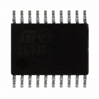
L6730TR STMicroelectronics, L6730TR Datasheet - Page 4

L6730TR
Manufacturer Part Number
L6730TR
Description
IC CTRLR ADJ STEP DOWN 20-TSSOP
Manufacturer
STMicroelectronics
Type
Step-Down (Buck)r
Datasheet
1.L6730TR.pdf
(52 pages)
Specifications of L6730TR
Internal Switch(s)
No
Synchronous Rectifier
Yes
Number Of Outputs
1
Voltage - Output
Adj to 0.6V
Frequency - Switching
100kHz ~ 1MHz
Voltage - Input
1.8 ~ 14 V
Operating Temperature
-40°C ~ 85°C
Mounting Type
Surface Mount
Package / Case
20-TSSOP Exposed Pad, 20-eTSSOP, 20-HTSSOP
Output Voltage
0.6 V
Input Voltage
1.8 V to 14 V
Maximum Operating Temperature
+ 85 C
Minimum Operating Temperature
- 40 C
For Use With
497-5868 - EVAL BOARD 30A 400KHZ L6730497-5501 - EVAL BOARD FOR L6730XX
Lead Free Status / RoHS Status
Lead free / RoHS Compliant
Current - Output
-
Power - Output
-
Lead Free Status / Rohs Status
Lead free / RoHS Compliant
Other names
497-5098-2
Available stocks
Company
Part Number
Manufacturer
Quantity
Price
Part Number:
L6730TR
Manufacturer:
ST
Quantity:
20 000
Summary description
1
4/52
Summary description
The controller is an integrated circuit designed using BiCMOS-DMOS, v5 (BCD5)
technology that provides complete control logic and protection for high performance, step-
down DC/DC and niPOL converters.
It is designed to drive N-Channel MOSFETs in a synchronous rectified buck converter
topology. The output voltage of the converter can be precisely regulated down to 600 mV,
with a maximum tolerance of ±0.8%, or to 1.2 V, when one of the internal references is used.
It is also possible to use an external reference from 0 V to 2.5 V.
The input voltage can range from 1.8 V to 14 V, while the supply voltage can range from 4.5
V to 14 V. High peak current gate drivers provide for fast switching to the external power
section and the output current can be in excess of 20 A, depending on the number of the
external MOSFETs used. The PWM duty cycle can range from 0% to 100% with a minimum
on-time (T
very high switching frequency possible.
The device provides voltage-mode control. It includes a 400 kHz free-running oscillator that
is adjustable from 100 kHz to 1 MHz. The error amplifier features a 10 MHz gain-bandwidth-
product and 5 V/µs slew-rate that permits to realize high converter bandwidth for fast
transient response. The device monitors the current by using the R
side and low-side MOSFET(s), eliminating the need for a current sensing resistor and
guaranteeing an effective over current-protection in all the application conditions. When
necessary, two different current limit protections can be externally set through two external
resistors. A leading edge adjustable blanking time is also available to avoid false over-
current-protection (OCP) intervention in every application condition.
It is possible to select the HICCUP mode or the constant current protection (L6730B) after
the soft-start phase.
During this phase constant current protection is provided. It is possible to select the sink-
source or the source-only mode capability (before the device powers on) by acting on a
multifunction pin (L6730). The L6730 disables the sink mode capability during the soft-start
in order to allow a proper start-up also in pre-biased output voltage conditions. The L6730B
can always sink current and, so it can be used to supply the DDR memory BUS termination.
Other features include Master-Slave synchronization (with 180° phase shift), Power-Good
with adjustable delay, over voltage-protection, feed back disconnection, selectable UVLO
threshold (5 V and 12 V Bus), and thermal shutdown. The HTSSOP20 package allows the
realization for very compact DC/DC converters.
ON(MIN)
) lower than 100 ns, making conversions with a very low duty cycle and
Doc ID 11938 Rev 3
DS(ON)
of both the high-
L6730 - L6730B


