ZL2106ALCN Intersil, ZL2106ALCN Datasheet
ZL2106ALCN
Specifications of ZL2106ALCN
Available stocks


Related parts for ZL2106ALCN

ZL2106ALCN Summary of contents
Page 1
... Copyright Intersil Americas Inc. 2009, 2010, 2011. All Rights Reserved Intersil (and design trademark owned by Intersil Corporation or one of its subsidiaries. All other trademarks mentioned are the property of their respective owners. “ZL2106EVAL1Z Evaluation Board”, USB Adapter “Thermal and Layout Guidelines for Digital-DC™ ...
Page 2
Typical Application Circuit The following application circuit represents a typical implementation of the ZL2106. For PMBus operation recommended to tie the enable pin (EN) to SGND. † DDC Bus ENABLE PGOOD †† SMBus Notes: ‡ ...
Page 3
Pin Configuration Pin Descriptions TYPE PIN LABEL (Note DGND PWR 3 SYNC I/O, M (Note 2) 4 VSET SCL I/O 7 SDA I/O 8 SALRT ...
Page 4
... The SYNC pin can be used as a logic pin, a clock input or a clock output. Ordering Information PART NUMBER (Note 4) ZL2106ALCN (Note 2) ZL2106ALCNT (Notes 1, 2) ZL2106ALCNTK (Notes 1, 2) ZL2106ALCF (Note 3) ZL2106ALCFT (Notes 1, 3) ZL2106ALCFTK (Notes 1, 3) ZL2106ALCF-01 (Note 3) ZL2106ALCFT-01 (Notes 1, 3) ZL2106ALCFTK-01 (Notes 1, 3) ...
Page 5
Table of Contents Absolute Maximum Ratings . . . . . . . . . . . . . . . . . . . . . . . . . . . . . . . . . . ...
Page 6
... +85° 1.4W A Pb-Free Reflow Profile . . . . . . . . . . . . . . . . . . . . . . . . . . . . . . . see link below http://www.intersil.com/pbfree/Pb-FreeReflow.asp Recommended Operating Conditions Input Supply Voltage Range, VDDP, VDDS (See Figure 14) VDDS tied to VR, VRA . . . . . . . . . . . . . . . . . . . . . . . . . . . . . . . . 4.5V to 5.5V VDDS tied to VR, VRA Floating . . . . . . . . . . . . . . . . . . . . . . . . 5.5V to 7.5V VR, VRA Floating .7.5V to 14V ...
Page 7
Electrical Specifications V DDP Boldface limits apply over the operating temperature range, -40°C to +85°C. PARAMETER Soft-start Delay Duration Accuracy Soft-start Ramp Duration Range Soft-start Ramp Duration Accuracy Logic Input/output Characteristics Logic Input Leakage Current Logic input low ...
Page 8
Electrical Specifications V DDP Boldface limits apply over the operating temperature range, -40°C to +85°C. PARAMETER VSEN Undervoltage Threshold VSEN Overvoltage Threshold VSEN Undervoltage Hysteresis VSEN Undervoltage/Overvoltage Fault Response Time Peak Current Limit Threshold Current Limit Set-point Accuracy Current Limit ...
Page 9
Typical Performance Curves switching frequency, temperature) may require de-rating to remain within the Safe Operating Area (SOA). V 1.4 1.3 1.2 1.1 1.0 0.9 0 (°C) J FIGURE 5. LOW-SIDE NORMALIZED FOR T ...
Page 10
ZL2106 Overview Digital-DC Architecture The ZL2106 is an innovative mixed-signal power conversion and power management IC based on Zilker Labs patented Digital-DC technology that provides an integrated, high performance step-down converter for point of load applications. The ZL2106 integrates all ...
Page 11
The ZL2106 integrates two N-channel power MOSFETs the top control MOSFET and QL is the bottom synchronous MOSFET. The amount of time that fraction of the total switching period is known as the ...
Page 12
Logic ZL high Open Multi- mode Pin R SET Logic Pinstrap low Settings FIGURE 13. PIN-STRAP AND RESISTOR SETTING EXAMPLES RESISTOR SETTINGS This method allows a greater range of adjustability when connecting a finite value resistor (in a specified range) ...
Page 13
STEP # STEP NAME 1 Power Applied Input voltage is applied to the ZL2106’s VDD pins (VDDP and VDDS). 2 Internal Memory Check The device will check for values stored in its internal memory. This step is also performed after ...
Page 14
The soft-start delay period begins when the EN pin is asserted and ends when the delay time expires. The soft-start delay period is set using the SS pin. Precise ramp delay timing mode reduces the delay time variations and is ...
Page 15
Power-good (PG) The ZL2106 provides a Power-good (PG) signal that indicates the output voltage is within a specified tolerance of its target level and no fault condition exists. By default, the PG pin will assert if the output is within ...
Page 16
TABLE 8. SWITCHING FREQUENCY SELECTION SYNC PIN LOW OPEN HIGH Resistor If the user wishes to run the ZL2106 at a frequency not listed in Table 8, the switching frequency can be set using an external resistor connected ...
Page 17
A good starting point is to select the output inductor ripple equal to the expected load transient step magnitude ( opp ostep Now the output inductance can be calculated ...
Page 18
C so that a discharged C B voltage droop excessively during SELECTION VRA This capacitor is used to both stabilize and provide noise filtering for the analog 5V reference supply. ...
Page 19
TABLE 12. RESISTOR SETTING FOR LOOP COMPENSATION G Q fsw/fn (dB) 33 0.150 69.147 33 0.150 41.577 33 0.300 115.000 33 0.300 69.147 33 0.300 41.577 33 0.300 25.000 33 0.600 69.147 33 0.600 41.577 33 0.600 25.000 In the ...
Page 20
Once the pre-configured soft-start ramp period has expired, the PG pin will be asserted (assuming the pre-bias voltage is not higher than the overvoltage limit). The PWM will then adjust its duty cycle to match the original target voltage and ...
Page 21
PMBus commands. Figure example of a basic pin-strap tracking configuration. The VTRK pin is an analog input that, when tracking mode is enabled, the voltage applied to the VTRK ...
Page 22
Tracking Configuration Figure 20 (A) Vout Time On Time On Time Off Rail Set Dly Rise Dly (Volts) (ms) (ms) (ms) Reference 1 Member 0 Tracking Configuration Figure 20 (B) Time On Time On Time Off Vout Set Rail Dly Rise Dly (Volts) (ms) (ms) (ms) Reference 1.8 15 ...
Page 23
I C/SMBus Communications 2 The ZL2106 provides an I C/SMBus digital interface that enables the user to configure all aspects of the device operation as well as monitor the input and output parameters. The ZL2106 can be 2 used ...
Page 24
Phase Spreading When multiple point of load converters share a common DC input supply desirable to adjust the clock phase offset of each device such that not all devices start to switch simultaneously. Setting each converter to start ...
Page 25
Fault Spreading Digital-DC devices can be configured to broadcast a fault event over the DDC bus to the other devices in the group. When a non-destructive fault occurs and the device is configured to shut down on a fault, the ...
Page 26
Revision History The revision history provided is for informational purposes only and is believed to be accurate, but not warranted. Please go to web to make sure you have the latest Rev. DATE REVISION 12/16/10 FN6852.4 Added following parts to ...
Page 27
... In Spec table, changed conditions for VRA and V2P5 Reference Output Voltage from “50mA” to “20mA” 10) In Spec table, added Reference Note 19 (Limits established by characterization and not production tested) to Soft-start Delay Duration in conditions. 11) Changed Part Numbers in Ordering Information from From “ZL2106ALBN, ZL2106ALBNT, ZL2106ALBNTK” to “ZL2106ALCN, ZL2106ALCNT, ZL2106ALCNTK” 27 ZL2106 CHANGE Low Threshold” ...
Page 28
... Accordingly, the reader is cautioned to verify that data sheets are current before placing orders. Information furnished by Intersil is believed to be accurate and reliable. However, no responsibility is assumed by Intersil or its subsidiaries for its use; nor for any infringements of patents or other rights of third parties which may result from its use. No license is granted by implication or otherwise under any patent or patent rights of Intersil or its subsidiaries. ...
Page 29
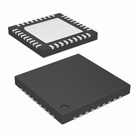
Package Outline Drawing L36.6x6A 36 LEAD QUAD FLAT NO-LEAD PLASTIC PACKAGE Rev 1, 9/09 6.00 6 PIN 1 INDEX AREA (4X) 0.15 TOP VIEW ( 5. 60 TYP ) ( TYPICAL RECOMMENDED LAND PATTERN 29 ZL2106 4X ...
Page 30
Package Outline Drawing L36.6x6C 36 LEAD QUAD FLAT NO-LEAD PLASTIC PACKAGE Rev 0, 4/10 6.00 6 PIN 1 INDEX AREA (4X) 0.15 TOP VIEW ( 5. 60 TYP ) ( TYPICAL RECOMMENDED LAND PATTERN 30 ZL2106 A ...