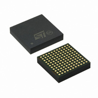
SPDC12L00010 STMicroelectronics, SPDC12L00010 Datasheet - Page 22

SPDC12L00010
Manufacturer Part Number
SPDC12L00010
Description
IC BUCK ADJ 10A 121LGA
Manufacturer
STMicroelectronics
Type
Point of Load (POL) Non-Isolated with UVLOr
Datasheet
1.SPDC12L00010.pdf
(29 pages)
Specifications of SPDC12L00010
Output
0.6 ~ 5V
Number Of Outputs
1
Power (watts)
50W
Mounting Type
Surface Mount
Voltage - Input
1.8 ~ 14V
Package / Case
121-LGA
1st Output
0.6 ~ 5 VDC @ 10A
Size / Dimension
0.59" L x 0.59" W x 0.11" H (15mm x 15mm x 2.8mm)
Power (watts) - Rated
50W
Operating Temperature
-40°C ~ 85°C
Efficiency
93%
Current - Output
10A
Voltage - Output
0.6 ~ 5 V
Frequency - Switching
729kHz
Synchronous Rectifier
No
Output Voltage
0.6 V to 5 V
Output Current
0 A to 10 A
Input Voltage
1.8 V to 14 V
Supply Current
65 mA
Switching Frequency
729 KHz
Maximum Operating Temperature
+ 85 C
Minimum Operating Temperature
- 40 C
Lead Free Status / RoHS Status
Lead free / RoHS Compliant
3rd Output
-
2nd Output
-
Lead Free Status / Rohs Status
Lead free / RoHS Compliant
Other names
497-9072
Available stocks
Company
Part Number
Manufacturer
Quantity
Price
Company:
Part Number:
SPDC12L00010
Manufacturer:
ADI
Quantity:
13
Application information
5.14
5.15
22/29
Figure 8.
Output over voltage protection
The device provides OVP:
when the voltage sensed on FB (pin L9) reaches a value greater than 20% of reference, the
on module low side driver is turned ON and the converter stop switching operation.
If the OVP not latched mode has been set, the on module low side MOSFET is kept ON, as
long as the over voltage condition is detected.
If OVP latched mode has been set, the low side MOSFET is turned ON and the OS (pin
K11) is forced high (4.5 V typ.), until VCC is toggled.
It must be taken in account that there is an electrical network between the output terminal
and FB, therefore the voltage at this pin is not a perfect replica of output voltage.
If the converter is set to sink current, the low side MOSFET could be turned ON before the
output voltage exceeds the over voltage threshold (109% typ.), because the error amplifier
will change its balance in advance.
If the sink-mode is disabled, the low side MOSFET will be turned ON only when the OVP
operate, in this case a delay between the output voltage rising and the FB rising can appear
and the OVP can operate late (126% typ.).
Current limitation
The device realizes the over current protection sensing the current on board high side
MOSFET and on board low side MOSFET, therefore two current limits are set:
peak current limit and valley current limit.
The peak current protection is active when the high side MOSFET is turned ON, the valley
current protection is enabled when the low side MOSFET is turned ON.
After soft-start is completed, if an over current occurs, the device enters in HICCUP mode:
both high side and low MOSFETs are turned OFF;
the soft-start capacitor is discharged with a 10 μA constant current;
when the voltage on SS_INL (pin L11) reaches 0.5 V the soft-start phase restart.
During the soft-start phase the OCP provides a constant current protection.
Additional loop compensation
Doc ID 15103 Rev 3
SPDC12L00010


