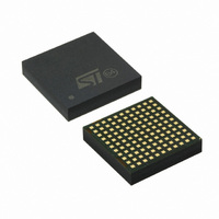
SPDC12L00010 STMicroelectronics, SPDC12L00010 Datasheet - Page 6

SPDC12L00010
Manufacturer Part Number
SPDC12L00010
Description
IC BUCK ADJ 10A 121LGA
Manufacturer
STMicroelectronics
Type
Point of Load (POL) Non-Isolated with UVLOr
Datasheet
1.SPDC12L00010.pdf
(29 pages)
Specifications of SPDC12L00010
Output
0.6 ~ 5V
Number Of Outputs
1
Power (watts)
50W
Mounting Type
Surface Mount
Voltage - Input
1.8 ~ 14V
Package / Case
121-LGA
1st Output
0.6 ~ 5 VDC @ 10A
Size / Dimension
0.59" L x 0.59" W x 0.11" H (15mm x 15mm x 2.8mm)
Power (watts) - Rated
50W
Operating Temperature
-40°C ~ 85°C
Efficiency
93%
Current - Output
10A
Voltage - Output
0.6 ~ 5 V
Frequency - Switching
729kHz
Synchronous Rectifier
No
Output Voltage
0.6 V to 5 V
Output Current
0 A to 10 A
Input Voltage
1.8 V to 14 V
Supply Current
65 mA
Switching Frequency
729 KHz
Maximum Operating Temperature
+ 85 C
Minimum Operating Temperature
- 40 C
Lead Free Status / RoHS Status
Lead free / RoHS Compliant
3rd Output
-
2nd Output
-
Lead Free Status / Rohs Status
Lead free / RoHS Compliant
Other names
497-9072
Available stocks
Company
Part Number
Manufacturer
Quantity
Price
Company:
Part Number:
SPDC12L00010
Manufacturer:
ADI
Quantity:
13
Pin settings
6/29
Table 2.
Bank 1
Bank 2
Bank 3
Bank 4
Name Function
L10
L11
L4
L5
L6
L7
L8
L9
SS_INL
PGDLY
COMP
SGND
PGND
SYNC
VOUT
PRG
VIN
PG
PH
FB
Pin description (continued)
Power Good.
This pin is an open collector output, with a 10 kΩ pull-up resistor connected to
VAUX.
It is pulled low if the output voltage is not within specified thresholds
(90%-110%).
Power Good delay.
A capacitor connected between this pin and SGND, introduce a delay between
the internal PG comparator and the external signal rising edge. No delay can be
introduced on the falling edge of PG signal.
Synchronization.
This is the master/slave pin. Two or more devices can be synchronized
connecting the SYNC pins together.
Program.
This pin allows following settings:
- Enable/disable the current sink mode capability after soft-start;
- Enable/disable the OVP latch mode;
- Setting UVLO threshold for 5 V or 12 V bus.
Signal ground.
All references are referred to these pins, internally connected to PGND.
Feed-back.
This pin is connected to the error amplifier inverting input.
Compensation.
This pin is connected to the error amplifier output.
Soft-start_inhibit low
The soft-start time is programmed connecting an external capacitor from this pin
to SGND;
This pin can be used to inhibit the module.
DC input voltage.
See
Return for input/output voltage source.
Regulated power output.
See
Phase
This pins area is foreseen for module power losses dissipation;
see
Section 5.20 on page 24
Section 5.18 on page 23
Section 5.19 on page 23
Doc ID 15103 Rev 3
for details.
for mandatory condition.
for mandatory condition.
Description
SPDC12L00010


