STEVAL-IHM015V1 STMicroelectronics, STEVAL-IHM015V1 Datasheet - Page 35
STEVAL-IHM015V1
Manufacturer Part Number
STEVAL-IHM015V1
Description
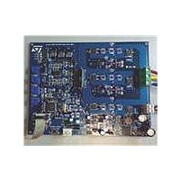
BOARD EVAL ST7FMC2S4T6/STS8DNH3L
Manufacturer
STMicroelectronics
Type
Motor / Motion Controllers & Driversr
Specifications of STEVAL-IHM015V1
Main Purpose
Power Management, Motor Control
Embedded
Yes, MCU, 8-Bit
Utilized Ic / Part
ST7FMC2S4, STS8DNH3LL
Primary Attributes
3-Ph BLAC, BLDC, PMAC or PMDC Motors
Secondary Attributes
Graphical User Interface
Input Voltage
5 V to 48 V
Product
Power Management Modules
Silicon Manufacturer
ST Micro
Core Architecture
ARM
Core Sub-architecture
ARM7TDMI
Silicon Core Number
ST7
Silicon Family Name
ST7MCx
Kit Contents
Board
Lead Free Status / RoHS Status
Lead free / RoHS Compliant
For Use With/related Products
ST7MC2S4, STS8DNH3LL
Other names
497-8213
Available stocks
Company
Part Number
Manufacturer
Quantity
Price
Company:

Part Number:
STEVAL-IHM015V1
Manufacturer:
STMicroelectronics
Quantity:
135


UM0432
Note:
7.4.12
7.4.13
Table 12.
Note:
7.4.14
J2
J3
J4
J21
Name
Open
Closed
Open
Closed
Between 1-2
Between 2-3
Open
Open
Between 1-2
Between 2-3
Selection
If an error message appears, make sure that the inDART-STX board is connected to the
ControlBDST7MC2 control board and that the control board is well supplied.
4.
Configuring the DC input range
Before supplying the board with the bus voltage, it must be configured by setting the J22,
J23, J24, J27 and J8 jumpers to the correct position. Refer to
jumper based on the DC input range and keep the J8 jumper between 1-2.
Jumper settings table
Jumper settings table
The default configuration is indicated with (*) in
Board connection
After the board has been programmed, the system can be configured as shown in
Figure
from the board if present.
1.
2.
(*)
(*)
(*)
After programming, check the action of the LED to verify that the firmware has been
correctly downloaded (see
Connect the insulated DC power supply to the J5 connector of STEVAL-IHM015V1,
following the serigraphy for polarity.
Connect the phases of the motor to the J10 connector of the board and if required,
connect the sensor signal to the hall sensor connector J14.
22. This configuration is called a running configuration. Remove the ICC flat cable
(*)
Disable the auxiliary Flash memory. The debug feature can be enabled.
Enable the auxiliary Flash memory. The debug feature cannot be enabled.
Disable the current reference generated by PWMV. The debug feature can be enabled
(this setting is not allowed when BLDC (trapezoidal) driving has been selected).
Enable the current reference generated by PWMV. The debug features cannot be
enabled.
Adjustable – the current reference value (MCCREF) is set by potentiometer P4. Only for
BLDC (trapezoidal) driving.
Variable – the current reference value (MCCREF) is driven by the microcontroller PWM-V.
Only for BLDC (trapezoidal) driving.
No current reference is required. For PMAC motor (sinewave) driving.
The threshold voltage used for BEMF detection is set internally by the microcontroller
firmware. This option should be selected for the ST BEMF detecting strategy.
The threshold voltage used for BEMF detection is derived from the phase voltage value.
This option should be selected for the GE BEMF detecting strategy.
The threshold voltage used for BEMF detection is derived from the bus voltage. This
option should be selected for the GE BEMF detecting strategy.
Section
7.5.3,
Description
Section
Table
12.
7.6.3, and
Table 4
Motor control operations
Section 7.7.3
to configure the
).
35/53
Related parts for STEVAL-IHM015V1
Image
Part Number
Description
Manufacturer
Datasheet
Request
R

Part Number:
Description:
BOARD EVAL FOR MEMS SENSORS
Manufacturer:
STMicroelectronics
Datasheet:

Part Number:
Description:
KIT DEV STARTER ST10F276Z5
Manufacturer:
STMicroelectronics
Datasheet:

Part Number:
Description:
BOARD EVAL HDMI $ VIDEO SWITCH
Manufacturer:
STMicroelectronics
Datasheet:

Part Number:
Description:
BOARD DEMO ACCELEROMETER DIL24
Manufacturer:
STMicroelectronics
Datasheet:

Part Number:
Description:
BOARD STLM75/STDS75/ST72F651
Manufacturer:
STMicroelectronics
Datasheet:

Part Number:
Description:
EVAL BOARD 3AXIS MEMS ACCELLRMTR
Manufacturer:
STMicroelectronics
Datasheet:

Part Number:
Description:
BOARD EVAL 8BIT MICRO + TDE1708
Manufacturer:
STMicroelectronics
Datasheet:

Part Number:
Description:
EVAL BOARD A/D TS4657
Manufacturer:
STMicroelectronics
Datasheet:

Part Number:
Description:
BOARD ADAPTER 20DIP LIS3LV02DL
Manufacturer:
STMicroelectronics
Datasheet:

Part Number:
Description:
BOARD DEMO STM8S207R6/LIS331DLH
Manufacturer:
STMicroelectronics
Datasheet:

Part Number:
Description:
STMicroelectronics [RIPPLE-CARRY BINARY COUNTER/DIVIDERS]
Manufacturer:
STMicroelectronics
Datasheet:
Part Number:
Description:
STMicroelectronics [LIQUID-CRYSTAL DISPLAY DRIVERS]
Manufacturer:
STMicroelectronics
Datasheet:
Part Number:
Description:
BOARD EVAL FOR MEMS SENSORS
Manufacturer:
STMicroelectronics
Datasheet: