STEVAL-IHM015V1 STMicroelectronics, STEVAL-IHM015V1 Datasheet - Page 38
STEVAL-IHM015V1
Manufacturer Part Number
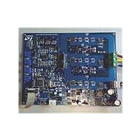
STEVAL-IHM015V1
Description
BOARD EVAL ST7FMC2S4T6/STS8DNH3L
Manufacturer
STMicroelectronics
Type
Motor / Motion Controllers & Driversr
Specifications of STEVAL-IHM015V1
Main Purpose
Power Management, Motor Control
Embedded
Yes, MCU, 8-Bit
Utilized Ic / Part
ST7FMC2S4, STS8DNH3LL
Primary Attributes
3-Ph BLAC, BLDC, PMAC or PMDC Motors
Secondary Attributes
Graphical User Interface
Input Voltage
5 V to 48 V
Product
Power Management Modules
Silicon Manufacturer
ST Micro
Core Architecture
ARM
Core Sub-architecture
ARM7TDMI
Silicon Core Number
ST7
Silicon Family Name
ST7MCx
Kit Contents
Board
Lead Free Status / RoHS Status
Lead free / RoHS Compliant
For Use With/related Products
ST7MC2S4, STS8DNH3LL
Other names
497-8213
Available stocks
Company
Part Number
Manufacturer
Quantity
Price
Company:

Part Number:
STEVAL-IHM015V1
Manufacturer:
STMicroelectronics
Quantity:
135


Motor control operations
7.5
7.5.1
7.5.2
7.5.3
7.5.4
7.5.5
38/53
Driving the BLDC motor (trapezoidal - sensorless)
This section describes how to drive the sensorless brushless permanent magnet motor. You
should first check that the board has been set-up for sensorless driving (see
Specific connection (sensor)
To also drive the motor in closed-loop mode, it is not necessary that the motor include any
position or speed sensor. For this demonstration we suggest using one Ametek BLDC
blower motor (voltage max 30 Vdc).
Specific jumper settings
Set-up the board following the instructions in
V) and
Table 14.
Set-up the board as per
LED action after power-on
Turn on the power supply. For this demonstration the power supply output voltage should be
set to 20 Vdc and the current limitation of the power supply should be set to 4 A.
After power-on, the control board LEDs should blink red, signaling that the firmware has
started to run. After a while a green LED stays on indicating an "idle" state.
Setting the potentiometers
Before running the motor, the three potentiometers P1, P2, P3 must be set (see
the correct configuration).
Running the motor (LED action)
Push the Start/Stop button. After pushing the button, the LEDs toggle from green to red to
indicate a "run" state. The motor starts to run.
BLDC_3PH_SL
Driving mode
Section
BLDC SL jumpers setting
7.4.13.
Table
14.
J11 between 2-3, J12 between 2-3, J13 between 1-2
J15 between 2-3, J16 between 2-3, J17 between 1-2
J18 between 2-3, J19 between 2-3, J20 between 1-2
J3 Closed, J4 variable (2-3)
Section 7.4.12
Jumper setting
(bus voltage between 9 and 28
Section
Table 15
UM0432
7.4.4).
for
Related parts for STEVAL-IHM015V1
Image
Part Number
Description
Manufacturer
Datasheet
Request
R

Part Number:
Description:
BOARD EVAL FOR MEMS SENSORS
Manufacturer:
STMicroelectronics
Datasheet:

Part Number:
Description:
KIT DEV STARTER ST10F276Z5
Manufacturer:
STMicroelectronics
Datasheet:

Part Number:
Description:
BOARD EVAL HDMI $ VIDEO SWITCH
Manufacturer:
STMicroelectronics
Datasheet:

Part Number:
Description:
BOARD DEMO ACCELEROMETER DIL24
Manufacturer:
STMicroelectronics
Datasheet:

Part Number:
Description:
BOARD STLM75/STDS75/ST72F651
Manufacturer:
STMicroelectronics
Datasheet:

Part Number:
Description:
EVAL BOARD 3AXIS MEMS ACCELLRMTR
Manufacturer:
STMicroelectronics
Datasheet:

Part Number:
Description:
BOARD EVAL 8BIT MICRO + TDE1708
Manufacturer:
STMicroelectronics
Datasheet:

Part Number:
Description:
EVAL BOARD A/D TS4657
Manufacturer:
STMicroelectronics
Datasheet:

Part Number:
Description:
BOARD ADAPTER 20DIP LIS3LV02DL
Manufacturer:
STMicroelectronics
Datasheet:

Part Number:
Description:
BOARD DEMO STM8S207R6/LIS331DLH
Manufacturer:
STMicroelectronics
Datasheet:

Part Number:
Description:
STMicroelectronics [RIPPLE-CARRY BINARY COUNTER/DIVIDERS]
Manufacturer:
STMicroelectronics
Datasheet:
Part Number:
Description:
STMicroelectronics [LIQUID-CRYSTAL DISPLAY DRIVERS]
Manufacturer:
STMicroelectronics
Datasheet:
Part Number:
Description:
BOARD EVAL FOR MEMS SENSORS
Manufacturer:
STMicroelectronics
Datasheet: