ADIS16265/PCBZ Analog Devices Inc, ADIS16265/PCBZ Datasheet - Page 14
ADIS16265/PCBZ
Manufacturer Part Number
ADIS16265/PCBZ
Description
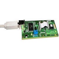
BOARD EVALUATION FOR ADIS16265
Manufacturer
Analog Devices Inc
Series
iMEMS®, iSensor™r
Datasheet
1.ADIS16260PCBZ.pdf
(20 pages)
Specifications of ADIS16265/PCBZ
Sensor Type
Gyroscope, 1 Axis
Sensing Range
±80°/sec, ±160°/sec, ±320°/sec
Sensitivity
±0.2%
Embedded
No
Utilized Ic / Part
ADIS16265
Silicon Manufacturer
Analog Devices
Application Sub Type
Angular Rate Sensor / Gyroscope
Kit Application Type
Sensing - Motion / Vibration / Shock
Silicon Core Number
ADIS16265
Lead Free Status / RoHS Status
Lead free / RoHS compliant by exemption
Voltage - Supply
-
Interface
-
Lead Free Status / RoHS Status
Lead free / RoHS compliant by exemption


ADIS16260/ADIS16265
Sensor Bandwidth
The gyroscope signal chain has several filter stages that shape
its frequency response. Figure 15 provides a block diagram of
each filter stage and Table 15 lists the SENS_AVG register con-
trols for bandwidth.
Table 15. SENS_AVG Bit Descriptions
Bits
[15:11]
[10:8]
[7]
[6:3]
[2:0]
Digital Filtering
A programmable low-pass filter provides additional opportu-
nity for noise reduction on the inertial sensor outputs. This
filter contains two cascaded averaging filters that provide a
Bartlett window, FIR filter response (see Figure 16). For example,
set SENS_AVG[2:0] = 100 (DIN = 0xB804) to set each stage to
16 taps. When used with the default sample rate of 256 SPS, this
reduces the bandwidth of the digital filter to approximately 5.2 Hz.
SENSOR
FROM
GYRO
RATE
–100
–120
–140
f
R = 90kΩ
C
Figure 16. Digital Filter Frequency, Bartlett Window FIR Filter
–20
–40
–60
–80
C
T
0.001
=
0
= C
Description (Default = 0x0402)
Not used.
Measurement range (sensitivity) selection.
100 = ±320°/sec (default condition).
010 = ±160°/sec, filter taps ≥ 4 (Bits[2:0] ≥ 0x02).
001 = ±80°/sec, filter taps ≥ 16 (Bits[2:0] ≥ 0x04).
Primary pole setting (k).
1: C
0: C
Not used.
Number of taps in each stage; value of m in N = 2
2
INT
C
f
C
× R × C
e
+ C
INT
INT
N = 2
N = 4
N = 16
N = 64
1
Figure 15. Signal Processing Diagram
e
= 0.0047 µF (bandwidth = 330 Hz).
= 0.0377 µF (bandwidth = 50 Hz).
FILT
T
740Hz
(Phase = N Samples)
0.01
FREQUENCY (
f
/
f
S
)
0.1
N = 2
m = SENS_AVG[2:0]
N
m
N
1
m
Rev. B | Page 14 of 20
.
Dynamic Range
The SENS_AVG[10:8] bits provide three dynamic range settings
for this gyroscope. The lower dynamic range settings (±80°/sec
and ±160°/sec) limit the minimum filter tap sizes to maintain
resolution. For example, set SENS_AVG[10:8] = 010 (DIN =
0xB902) for a measurement range of ±160°/sec. Because this
setting can influence the filter settings, program SENS_AVG[10:8]
and then SENS_AVG[2:0] if more filtering is required.
Calibration
The GYRO_OFF and GYRO_SCALE registers provide user
controls for making in-system adjustments to offset and scale
factor.
Table 16. GYRO_OFF Bit Descriptions
Bits
[15:12]
[11:0]
Table 17. GYRO_SCALE Bit Descriptions
Bits
[15:12]
[11:0]
FROM INTERNAL
PROCESSING
Description (Default = 0x0000)
Not used.
Offset adjustment factor, twos complement format,
0.018315°/sec per LSB.
Examples:
0x000: Add 0°/sec to gyroscope data.
0x001: Add 0.018315°/sec to gyroscope data.
0x0AA: Add 3.11355°/sec to gyroscope data.
0xF0F: Subtract 4.41392°/sec from gyroscope data.
0xFFF: Subtract 0.018315°/sec from gyroscope data.
Description (Default = 0x0800)
Not used.
Scale adjustment factor, offset binary format,
0.00048828/LSB.
Examples:
0x000: Multiply output by 0.
0x7F0: Multiply gyroscope data by 0.99218.
0x800: Multiply output by 1.
0x8A0: Multiply output by 1.077812.
0xFFF: Multiply output by 1.9995.
Figure 17. User Calibration Registers
GYRO_OFF
GYRO_SCALE
TO OUTPUT
REGISTERS
Related parts for ADIS16265/PCBZ
Image
Part Number
Description
Manufacturer
Datasheet
Request
R

Part Number:
Description:
±1.7g Dual-Axis IMEMS Accelerometer Evaluation Board
Manufacturer:
Analog Devices Inc
Datasheet:

Part Number:
Description:
Inertial Sensor Evaluation System
Manufacturer:
Analog Devices Inc
Datasheet:
Part Number:
Description:
Manufacturer:
Analog Devices Inc
Datasheet:
Part Number:
Description:
Manufacturer:
Analog Devices Inc
Datasheet:
Part Number:
Description:
Manufacturer:
Analog Devices Inc
Datasheet:
Part Number:
Description:
Manufacturer:
Analog Devices Inc
Datasheet:
Part Number:
Description:
Manufacturer:
Analog Devices Inc
Datasheet:
Part Number:
Description:
Manufacturer:
Analog Devices Inc
Datasheet:
Part Number:
Description:
Manufacturer:
Analog Devices Inc
Datasheet:
Part Number:
Description:
Manufacturer:
Analog Devices Inc
Datasheet:
Part Number:
Description:
Manufacturer:
Analog Devices Inc
Datasheet:
Part Number:
Description:
Manufacturer:
Analog Devices Inc
Datasheet:
Part Number:
Description:
Manufacturer:
Analog Devices Inc
Datasheet: