ADIS16265/PCBZ Analog Devices Inc, ADIS16265/PCBZ Datasheet - Page 16
ADIS16265/PCBZ
Manufacturer Part Number
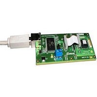
ADIS16265/PCBZ
Description
BOARD EVALUATION FOR ADIS16265
Manufacturer
Analog Devices Inc
Series
iMEMS®, iSensor™r
Datasheet
1.ADIS16260PCBZ.pdf
(20 pages)
Specifications of ADIS16265/PCBZ
Sensor Type
Gyroscope, 1 Axis
Sensing Range
±80°/sec, ±160°/sec, ±320°/sec
Sensitivity
±0.2%
Embedded
No
Utilized Ic / Part
ADIS16265
Silicon Manufacturer
Analog Devices
Application Sub Type
Angular Rate Sensor / Gyroscope
Kit Application Type
Sensing - Motion / Vibration / Shock
Silicon Core Number
ADIS16265
Lead Free Status / RoHS Status
Lead free / RoHS compliant by exemption
Voltage - Supply
-
Interface
-
Lead Free Status / RoHS Status
Lead free / RoHS compliant by exemption


ADIS16260/ADIS16265
DIAGNOSTICS
Self-Test
The self-test function allows the user to verify the mechanical
integrity of each MEMS sensor. It applies an electrostatic force
to each sensor element, which results in mechanical displace-
ment that simulates a response to actual motion. Table 1 lists
the expected response for each sensor, which provides pass/fail
criteria.
Set MSC_CTRL[10] = 1 (DIN = 0xB504) to run the internal
self-test routine, which exercises the inertial sensor, measures
the response, makes a pass/fail decision, reports the decision to
error flags in the DIAG_STAT register, and then restores normal
operation. MSC_CTRL[10] resets itself to 0 after completing the
routine. The MSC_CTRL[9:8] bits provide manual control of the
self-test function for investigation of potential failures. Table 24
outlines an example test flow for using this option to verify the
gyroscope function.
Table 24. Manual Self-Test Example Sequence
DIN
0xB601
0xB904
0xB802
0x0400
0xB502
0x0400
0xB501
0x0400
0xB500
Zero motion provides results that are more reliable. The settings
in Table 24 are flexible and allow for optimization around speed
and noise influence. For example, using fewer filtering taps
decreases delay times but increases the potential for noise
influence.
Memory Test
Setting MSC_CTRL[11] = 1 (DIN = 0xB508) performs a check-
sum comparison between the flash memory and SRAM to help
verify memory integrity. The pass/fail result is loaded into the
DIAG_STAT[6] register.
Description
SMPL_PRD[7:0] = 0x01, sample rate = 256 SPS.
SENS_AVG[15:8] = 0x04, gyro range = ±320°/sec.
SENS_AVG[7:0] = 0x02, four-tap averaging filter.
Delay = 50 ms.
Read GYRO_OUT.
MSC_CTRL[9:8] = 10, gyroscope negative self-test.
Delay = 50 ms.
Read GYRO_OUT.
Determine whether the bias in the gyroscope
output changed according to the self-test
response specified in Table 1.
MSC_CTRL[9:8] = 01, gyroscope/accelerometer
positive self-test.
Delay = 50 ms.
Read GYRO_OUT.
Determine whether the bias in the gyroscope
output changed according to the self-test
response specified in Table 1.
MSC_CTRL[15:8] = 0x00.
Rev. B | Page 16 of 20
Status
The error flags provide indicator functions for common
system level issues. All of the flags are cleared (set to 0) after
each DIAG_STAT register read cycle. If an error condition
remains, the error flag returns to 1 during the next sample
cycle. DIAG_STAT[1:0] does not require a read of this register
to return to 0. If the power supply voltage goes back into range,
these two flags are cleared automatically.
Table 25. DIAG_STAT Bit Descriptions
Bits
[15:10]
[9]
[8]
[7]
[6]
[5]
[4]
[3]
[2]
[1]
[0]
Alarm Registers
The alarm function provides monitoring for two independent
conditions. The ALM_CTRL register provides control inputs
for data source, data filtering (prior to comparison), static
comparison, dynamic rate-of-change comparison, and output
indicator configurations. The ALM_MAGx registers establish
the trigger threshold and polarity configurations. Table 29 gives
an example of how to configure a static alarm. The ALM_SMPLx
registers provide the numbers of samples to use in the dynamic
rate-of-change configuration. The period equals the number in
the ALM_SMPLx register multiplied by the sample period time,
which is established by the SMPL_PRD register. See Table 30 for
an example of how to configure the sensor for this type of function.
Table 26. ALM_MAG1, ALM_MAG2 Bit Descriptions
Bits
[15]
[14]
[13:0]
Table 27. ALM_SMPL1, ALM_SMPL2 Bit Descriptions
Bits
[15:8]
[7:0]
Description (Default = 0x0000)
Comparison polarity
(1 = greater than, 0 = less than).
Not used.
Data bits that match the format of the trigger source
selection.
Description (Default = 0x0000)
Not used.
Data bits: number of samples (both 0x00 and 0x01 = 1).
Description
Not used.
Alarm 2 status (1 = active, 0 = inactive).
Alarm 1 status (1 = active, 0 = inactive).
Not used.
Flash test, checksum flag (1 = fail, 0 = pass).
Self-test diagnostic error flag (1 = fail, 0 = pass).
Sensor overrange (1 = fail, 0 = pass).
SPI communication failure (1 = fail, 0 = pass).
Flash update failure (1 = fail, 0 = pass).
Power supply > 5.25 V.
1 = power supply > 5.25 V, 0 = power supply ≤ 5.25 V.
Power supply < 4.75 V.
1 = power supply < 4.75 V, 0 = power supply ≥ 4.75 V.
Related parts for ADIS16265/PCBZ
Image
Part Number
Description
Manufacturer
Datasheet
Request
R

Part Number:
Description:
±1.7g Dual-Axis IMEMS Accelerometer Evaluation Board
Manufacturer:
Analog Devices Inc
Datasheet:

Part Number:
Description:
Inertial Sensor Evaluation System
Manufacturer:
Analog Devices Inc
Datasheet:
Part Number:
Description:
Manufacturer:
Analog Devices Inc
Datasheet:
Part Number:
Description:
Manufacturer:
Analog Devices Inc
Datasheet:
Part Number:
Description:
Manufacturer:
Analog Devices Inc
Datasheet:
Part Number:
Description:
Manufacturer:
Analog Devices Inc
Datasheet:
Part Number:
Description:
Manufacturer:
Analog Devices Inc
Datasheet:
Part Number:
Description:
Manufacturer:
Analog Devices Inc
Datasheet:
Part Number:
Description:
Manufacturer:
Analog Devices Inc
Datasheet:
Part Number:
Description:
Manufacturer:
Analog Devices Inc
Datasheet:
Part Number:
Description:
Manufacturer:
Analog Devices Inc
Datasheet:
Part Number:
Description:
Manufacturer:
Analog Devices Inc
Datasheet:
Part Number:
Description:
Manufacturer:
Analog Devices Inc
Datasheet: