CYII4SM6600-EVAL Cypress Semiconductor Corp, CYII4SM6600-EVAL Datasheet - Page 32
CYII4SM6600-EVAL
Manufacturer Part Number
CYII4SM6600-EVAL
Description
BOARD EVAL IMAGE SENS IBIS4-6600
Manufacturer
Cypress Semiconductor Corp
Datasheet
1.CYII4SC6600-EVAL.pdf
(34 pages)
Specifications of CYII4SM6600-EVAL
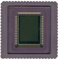
Sensor Type
CMOS Imaging, Monochrome
Sensing Range
6.6 Megapixel
Interface
SPI
Sensitivity
89 fps
Voltage - Supply
2.5 V ~ 3.3 V
Embedded
No
Utilized Ic / Part
IBIS4-6600
Lead Free Status / RoHS Status
Contains lead / RoHS non-compliant
Lead Free Status / RoHS Status
Lead free / RoHS Compliant, Contains lead / RoHS non-compliant


Glass Lid Specifications
Monochrome Sensor
A D263 glass is used as protection glass lid on top of the IBIS4-6600 monochrome sensors. The refraction index of the D263 glass
lid is 1.52.
Storage and Handling
Storage Conditions
Table 16. Storage Conditions
Handling and Soldering Conditions
Special care must be taken when soldering image sensors with
color filter arrays (RGB color filters), onto a circuit board,
because color filters are sensitive to high temperatures.
Prolonged heating at elevated temperatures may result in
deterioration of the performance of the sensor. The following
recommendations ensure that sensor performance is not
compromised during end-users assembly processes.
Board Assembly
Device placement onto boards must be done in accordance with
strict ESD controls for Class 0, JESD22 Human Body Model, and
Class A, JESD22 Machine Model devices. Assembly operators
must always wear all designated and approved grounding
equipment.
workstations are recommended, including the use of ionized
blowers. All tools must be ESD protected.
Document Number: 001-02366 Rev. *G
Temperature
Description
Figure 30
Grounded
Minimum
shows the transmission characteristics of the D263 glass.
–30
wrist
100
90
80
70
60
50
40
30
20
10
0
400
Figure 30. Transmittance Curve of the D263 Cover Glass Lid
Maximum
straps
+85
at
500
ESD
Maximum
°C
protected
Wavelength [nm]
600
Manual Soldering
When a soldering iron is used, the following conditions must be
observed:
■
■
Reflow Soldering
Figure 31
thermal profile for a reflow soldering system. If the
temperature/time profile exceeds these recommendations,
damage to the image sensor may occur. See
33 for more details.
Precautions and Cleaning
Avoid spilling solder flux on the cover glass, because bare glass
and particularly glass with antireflection filters may be adversely
affected by the flux. Avoid mechanical or particulate damage to
the cover glass.
It is recommended that isopropyl alcohol (IPA) be used as a
solvent for cleaning the image sensor glass lid. When using other
solvents, it must be confirmed beforehand whether the solvent
can dissolve the package and/or the glass lid.
Use a soldering iron with temperature control at the tip. The
soldering iron tip temperature must not exceed 350°C.
The soldering period for each pin must be less than 5 seconds.
700
on page 33 shows the maximum recommended
IBIS4-6600 CYII4SM6600AB
800
900
Figure 31
Page 32 of 34
on page
[+] Feedback
Related parts for CYII4SM6600-EVAL
Image
Part Number
Description
Manufacturer
Datasheet
Request
R

Part Number:
Description:
Manufacturer:
Cypress Semiconductor Corp
Datasheet:
Part Number:
Description:
Manufacturer:
Cypress Semiconductor Corp
Datasheet:
Part Number:
Description:
Manufacturer:
Cypress Semiconductor Corp
Datasheet:
Part Number:
Description:
Manufacturer:
Cypress Semiconductor Corp
Datasheet:
Part Number:
Description:
Manufacturer:
Cypress Semiconductor Corp
Datasheet: