C8051F360DK Silicon Laboratories Inc, C8051F360DK Datasheet - Page 207
C8051F360DK
Manufacturer Part Number
C8051F360DK
Description
KIT DEV FOR C8051F360 FAMILY
Manufacturer
Silicon Laboratories Inc
Type
MCUr
Specifications of C8051F360DK
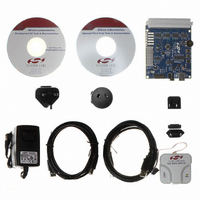
Contents
Evaluation Board, Power Supply, USB Cables, Adapter and Documentation
Processor To Be Evaluated
C8051F36x
Interface Type
USB
Lead Free Status / RoHS Status
Lead free / RoHS Compliant
For Use With/related Products
C8051F360, F361, F362, F363, F364, F365, F366, F367, F368, F369
Lead Free Status / Rohs Status
Lead free / RoHS Compliant
Other names
336-1410


Figure 18.4 shows the typical SCL generation described by Equation 18.2. Notice that T
twice as large as T
extended low by slower slave devices, or driven low by contending master devices). The bit rate when
operating as a master will never exceed the limits defined by equation Equation 18.1.
Setting the EXTHOLD bit extends the minimum setup and hold times for the SDA line. The minimum SDA
setup time defines the absolute minimum time that SDA is stable before SCL transitions from low-to-high.
The minimum SDA hold time defines the absolute minimum time that the current SDA value remains stable
after SCL transitions from high-to-low. EXTHOLD should be set so that the minimum setup and hold times
meet the SMBus Specification requirements of 250 ns and 300 ns, respectively. Table 18.2 shows the min-
imum setup and hold times for the two EXTHOLD settings. Setup and hold time extensions are typically
necessary when SYSCLK is above 10 MHz.
With the SMBTOE bit set, Timer 3 should be configured to overflow after 25 ms in order to detect SCL low
timeouts (see Section “18.3.3. SCL Low Timeout” on page 204). The SMBus interface will force Timer 3 to
reload while SCL is high, and allow Timer 3 to count when SCL is low. The Timer 3 interrupt service routine
should be used to reset SMBus communication by disabling and re-enabling the SMBus.
SMBus Free Timeout detection can be enabled by setting the SMBFTE bit. When this bit is set, the bus will
be considered free if SDA and SCL remain high for more than 10 SMBus clock source periods (see
Figure 18.4). When a Free Timeout is detected, the interface will respond as if a STOP was detected (an
interrupt will be generated, and STO will be set).
Timer Source
Overflows
SCL
*Note: Setup Time for ACK bit transmissions and the MSB of all data transfers. The s/w
EXTHOLD
delay occurs between the time SMB0DAT or ACK is written and when SI is cleared.
Note that if SI is cleared in the same write that defines the outgoing ACK value, s/w
delay is zero.
0
1
LOW
Table 18.2. Minimum SDA Setup and Hold Times
T
. The actual SCL output may vary due to other devices on the bus (SCL may be
Low
Figure 18.4. Typical SMBus SCL Generation
Minimum SDA Setup Time
1 system clock + s/w delay*
T
low
11 system clocks
– 4 system clocks
T
High
or
C8051F360/1/2/3/4/5/6/7/8/9
Rev. 1.0
Minimum SDA Hold Time
12 system clocks
3 system clocks
SCL High Timeout
HIGH
is typically
207
Related parts for C8051F360DK
Image
Part Number
Description
Manufacturer
Datasheet
Request
R

Part Number:
Description:
SMD/C°/SINGLE-ENDED OUTPUT SILICON OSCILLATOR
Manufacturer:
Silicon Laboratories Inc
Part Number:
Description:
Manufacturer:
Silicon Laboratories Inc
Datasheet:
Part Number:
Description:
N/A N/A/SI4010 AES KEYFOB DEMO WITH LCD RX
Manufacturer:
Silicon Laboratories Inc
Datasheet:
Part Number:
Description:
N/A N/A/SI4010 SIMPLIFIED KEY FOB DEMO WITH LED RX
Manufacturer:
Silicon Laboratories Inc
Datasheet:
Part Number:
Description:
N/A/-40 TO 85 OC/EZLINK MODULE; F930/4432 HIGH BAND (REV E/B1)
Manufacturer:
Silicon Laboratories Inc
Part Number:
Description:
EZLink Module; F930/4432 Low Band (rev e/B1)
Manufacturer:
Silicon Laboratories Inc
Part Number:
Description:
I°/4460 10 DBM RADIO TEST CARD 434 MHZ
Manufacturer:
Silicon Laboratories Inc
Part Number:
Description:
I°/4461 14 DBM RADIO TEST CARD 868 MHZ
Manufacturer:
Silicon Laboratories Inc
Part Number:
Description:
I°/4463 20 DBM RFSWITCH RADIO TEST CARD 460 MHZ
Manufacturer:
Silicon Laboratories Inc
Part Number:
Description:
I°/4463 20 DBM RADIO TEST CARD 868 MHZ
Manufacturer:
Silicon Laboratories Inc
Part Number:
Description:
I°/4463 27 DBM RADIO TEST CARD 868 MHZ
Manufacturer:
Silicon Laboratories Inc
Part Number:
Description:
I°/4463 SKYWORKS 30 DBM RADIO TEST CARD 915 MHZ
Manufacturer:
Silicon Laboratories Inc
Part Number:
Description:
N/A N/A/-40 TO 85 OC/4463 RFMD 30 DBM RADIO TEST CARD 915 MHZ
Manufacturer:
Silicon Laboratories Inc
Part Number:
Description:
I°/4463 20 DBM RADIO TEST CARD 169 MHZ
Manufacturer:
Silicon Laboratories Inc