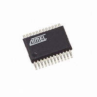
T89C5121-ICUIL Atmel, T89C5121-ICUIL Datasheet - Page 18

T89C5121-ICUIL
Manufacturer Part Number
T89C5121-ICUIL
Description
IC 8051 MCU W/SMART CARD 24SSOP
Manufacturer
Atmel
Series
89Cr
Datasheet
1.89C5121-SK1.pdf
(115 pages)
Specifications of T89C5121-ICUIL
Core Processor
8051
Core Size
8-Bit
Speed
16MHz
Connectivity
SmartCard, UART/USART
Peripherals
LED, POR, WDT
Number Of I /o
14
Program Memory Size
16KB (16K x 8)
Program Memory Type
Flash RAM
Eeprom Size
16K x 8
Ram Size
256 x 8
Voltage - Supply (vcc/vdd)
2.85 V ~ 5.4 V
Oscillator Type
Internal
Operating Temperature
-40°C ~ 85°C
Package / Case
24-SSOP
Lead Free Status / RoHS Status
Contains lead / RoHS non-compliant
Data Converters
-
Other names
Q1468934
T89C5121-ICSIL
T89C5121-ICSIL
T89C5121-ICSIL
T89C5121-ICSIL
- Current page: 18 of 115
- Download datasheet (838Kb)
Reduced EMI Mode
Power Modes Control
Registers
18
A/T8xC5121
The ALE signal is used to demultiplex address and data buses on port 0 when used with
external program or data memory. Nevertheless, during internal code execution, ALE
signal is still generated.
Only in case of PLCC52 version, in order to reduce EMI, ALE signal can be disabled by
setting AO bit.
The AO bit is located in AUXR register at bit location 0 (See Table 4). As soon as AO is
set, ALE is no longer output but remains active during MOVX and MOVC instructions
and external fetches. During ALE disabling, ALE pin is weakly pulled high.
Table 3. PCON Register
PCON (S:87h)
Power Configuration Register
Reset Value = X0XX XX00b
Number
SMOD1
Bit
7
6
5
4
3
2
1
0
7
Mnemonic Description
SMOD1
SMOD0
LEDPD
SMOD0
GF0
Bit
PD
IDL
6
Double Baud Rate bit
Set to double the Baud Rate when Timer 1 is used and mode 1, 2 or 3 is selected in
SCON register.
SCON Select bit
When cleared, read/write accesses to SCON.7 are to SM0 bit and read/write
accesses to SCON.6 are to SM1 bit.
When set, read/write accesses to SCON.7 are to FE bit and read/write accesses to
SCON.6 are to OVR bit. SCON is Serial Port Control register.
Reserved
Reserved
LED Control Power-Down Mode bits
When cleaned the I/O pull-up is the standard C51 pull-up control. When set the
medium pull-up is disconnected.
General-purpose flag 0
One use is to indicate wether an interrupt occurred during normal operation or
during Idle mode.
Power-down Mode bit
Cleared by hardware when an interrupt or reset occurs.
Set to activate the Power-down mode.
If IDL and PD are both set, PD takes precedence.
Idle Mode bit
Cleared by hardware when an interrupt or reset occurs.
Set to activate the Idle mode.
If IDL and PD are both set, PD takes precedence.
5
-
4
-
LEDPD
3
GF0
2
PD
1
4164G–SCR–07/06
IDL
0
Related parts for T89C5121-ICUIL
Image
Part Number
Description
Manufacturer
Datasheet
Request
R

Part Number:
Description:
8-bit Microcontroller with MULTI-PROTOCOL SMART CARD INTERFACE
Manufacturer:
ATMEL [ATMEL Corporation]
Datasheet:

Part Number:
Description:
MCU, MPU & DSP Development Tools C5121 Starter kit
Manufacturer:
Atmel

Part Number:
Description:
KIT SMART CARD FOR AT89C5121
Manufacturer:
Atmel
Datasheet:

Part Number:
Description:
DEV KIT FOR AVR/AVR32
Manufacturer:
Atmel
Datasheet:

Part Number:
Description:
INTERVAL AND WIPE/WASH WIPER CONTROL IC WITH DELAY
Manufacturer:
ATMEL Corporation
Datasheet:

Part Number:
Description:
Low-Voltage Voice-Switched IC for Hands-Free Operation
Manufacturer:
ATMEL Corporation
Datasheet:

Part Number:
Description:
MONOLITHIC INTEGRATED FEATUREPHONE CIRCUIT
Manufacturer:
ATMEL Corporation
Datasheet:

Part Number:
Description:
AM-FM Receiver IC U4255BM-M
Manufacturer:
ATMEL Corporation
Datasheet:

Part Number:
Description:
Monolithic Integrated Feature Phone Circuit
Manufacturer:
ATMEL Corporation
Datasheet:

Part Number:
Description:
Multistandard Video-IF and Quasi Parallel Sound Processing
Manufacturer:
ATMEL Corporation
Datasheet:

Part Number:
Description:
High-performance EE PLD
Manufacturer:
ATMEL Corporation
Datasheet:

Part Number:
Description:
8-bit Flash Microcontroller
Manufacturer:
ATMEL Corporation
Datasheet:


