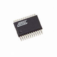
T89C5121-ICUIL Atmel, T89C5121-ICUIL Datasheet - Page 74

T89C5121-ICUIL
Manufacturer Part Number
T89C5121-ICUIL
Description
IC 8051 MCU W/SMART CARD 24SSOP
Manufacturer
Atmel
Series
89Cr
Datasheet
1.89C5121-SK1.pdf
(115 pages)
Specifications of T89C5121-ICUIL
Core Processor
8051
Core Size
8-Bit
Speed
16MHz
Connectivity
SmartCard, UART/USART
Peripherals
LED, POR, WDT
Number Of I /o
14
Program Memory Size
16KB (16K x 8)
Program Memory Type
Flash RAM
Eeprom Size
16K x 8
Ram Size
256 x 8
Voltage - Supply (vcc/vdd)
2.85 V ~ 5.4 V
Oscillator Type
Internal
Operating Temperature
-40°C ~ 85°C
Package / Case
24-SSOP
Lead Free Status / RoHS Status
Contains lead / RoHS non-compliant
Data Converters
-
Other names
Q1468934
T89C5121-ICSIL
T89C5121-ICSIL
T89C5121-ICSIL
T89C5121-ICSIL
- Current page: 74 of 115
- Download datasheet (838Kb)
Timer 0
Mode 0 (13-bit Timer 0)
Figure 28. Timer 0/Counter x (x = 0 or 1) in Mode 0
Mode 1 (16-bit Timer 0)
74
INTx#
A/T8xC5121
Tx
FCLK_Periph
TMOD reg
GATEx
TMOD reg
C/Tx#
Timer 0 functions as either a Timer 0 or an event Counter in four operating modes.
Figure 28 through Figure 31 show the logic configuration of each mode.
Timer 0 is controlled by the four lower bits of the TMOD register (see Figure 56) and bits
0, 1, 4 and 5 of the TCON register (see Figure 55). The TMOD register selects the
method of Timer 0 gating (GATE0), Timer 0 or Counter operation (T/C0#) and the oper-
ating mode (M10 and M00). The TCON register provides Timer 0 control functions:
overflow flag (TF0), run control bit (TR0), interrupt flag (IE0) and interrupt type control bit
(IT0).
For normal Timer 0 operation (GATE0 = 0), setting TR0 allows TL0 to be incremented
by the selected input. Setting GATE0 and TR0 allows external pin
operation.
Timer 0 overflow (count rolls over from all 1s to all 0s) sets the TF0 flag and generates
an interrupt request.
It is important to stop the Timer 0/Counter before changing modes.
Mode 0 configures Timer 0 as a 13-bit Timer 0 which is set up as an 8-bit Timer 0 (TH0
register) with a module-32 prescaler implemented with the lower five bits of the TL0 reg-
ister (see Figure 28). The upper three bits of the TL0 register are indeterminate and
should be ignored. Prescaler overflow increments the TH0 register.
Mode 1 configures Timer 0 as a 16-bit Timer 0 with the TH0 and TL0 registers con-
nected in a cascade (see Figure 29). The selected input increments the TL0 register.
0
1
TCON reg
TRx
(8 bits)
THx
(5 bits)
TLx
Overflow
TCON reg
TFx
INT0
to control Timer 0
Timer 0 x
Interrupt
Request
4164G–SCR–07/06
Related parts for T89C5121-ICUIL
Image
Part Number
Description
Manufacturer
Datasheet
Request
R

Part Number:
Description:
8-bit Microcontroller with MULTI-PROTOCOL SMART CARD INTERFACE
Manufacturer:
ATMEL [ATMEL Corporation]
Datasheet:

Part Number:
Description:
MCU, MPU & DSP Development Tools C5121 Starter kit
Manufacturer:
Atmel

Part Number:
Description:
KIT SMART CARD FOR AT89C5121
Manufacturer:
Atmel
Datasheet:

Part Number:
Description:
DEV KIT FOR AVR/AVR32
Manufacturer:
Atmel
Datasheet:

Part Number:
Description:
INTERVAL AND WIPE/WASH WIPER CONTROL IC WITH DELAY
Manufacturer:
ATMEL Corporation
Datasheet:

Part Number:
Description:
Low-Voltage Voice-Switched IC for Hands-Free Operation
Manufacturer:
ATMEL Corporation
Datasheet:

Part Number:
Description:
MONOLITHIC INTEGRATED FEATUREPHONE CIRCUIT
Manufacturer:
ATMEL Corporation
Datasheet:

Part Number:
Description:
AM-FM Receiver IC U4255BM-M
Manufacturer:
ATMEL Corporation
Datasheet:

Part Number:
Description:
Monolithic Integrated Feature Phone Circuit
Manufacturer:
ATMEL Corporation
Datasheet:

Part Number:
Description:
Multistandard Video-IF and Quasi Parallel Sound Processing
Manufacturer:
ATMEL Corporation
Datasheet:

Part Number:
Description:
High-performance EE PLD
Manufacturer:
ATMEL Corporation
Datasheet:

Part Number:
Description:
8-bit Flash Microcontroller
Manufacturer:
ATMEL Corporation
Datasheet:


