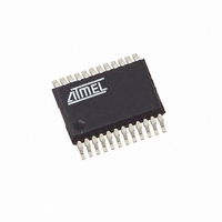
T89C5121-ICUIL Atmel, T89C5121-ICUIL Datasheet - Page 98

T89C5121-ICUIL
Manufacturer Part Number
T89C5121-ICUIL
Description
IC 8051 MCU W/SMART CARD 24SSOP
Manufacturer
Atmel
Series
89Cr
Datasheet
1.89C5121-SK1.pdf
(115 pages)
Specifications of T89C5121-ICUIL
Core Processor
8051
Core Size
8-Bit
Speed
16MHz
Connectivity
SmartCard, UART/USART
Peripherals
LED, POR, WDT
Number Of I /o
14
Program Memory Size
16KB (16K x 8)
Program Memory Type
Flash RAM
Eeprom Size
16K x 8
Ram Size
256 x 8
Voltage - Supply (vcc/vdd)
2.85 V ~ 5.4 V
Oscillator Type
Internal
Operating Temperature
-40°C ~ 85°C
Package / Case
24-SSOP
Lead Free Status / RoHS Status
Contains lead / RoHS non-compliant
Data Converters
-
Other names
Q1468934
T89C5121-ICSIL
T89C5121-ICSIL
T89C5121-ICSIL
T89C5121-ICSIL
- Current page: 98 of 115
- Download datasheet (838Kb)
Electrical Characteristics
Absolute Maximum Ratings
DC Parameters
98
Ambiant Temperature Under Bias ......................-25 C to 85 C
Storage Temperature ................................... -65 C to + 150 C
Voltage on
Voltage on Any Pin to V
A/T8xC5121
V
CC
to V
SS
........................................-0.5V to + 6.0V
SS
.......................... -0.5V to
T
Table 72. Core DC Parameters (XTAL, RST, P0, P2, ALE, PSEN, EA)
A
Symbol
= -40 C to +85 C; V
t
V
V
DV
Iccop
rise,
DI
V
V
V
V
PFDM
V
Icc
Icc
PFDP
t
IH1
OH
OL
G
IH
CC
IL
CC
t
fall
Parameter
Input Low Voltage
Input High Voltage
except XTAL1, RST
Input High Voltage,
XTAL1, RST
Output Low Voltage,
Port 0 and 2
Output High Voltage,
Port 0 and 2
Digital Supply Output
Current
Digital Supply
Voltage
Normal Power Down
mode
Pulsed Power Down
mode
Power Supply
current
Power-fail high level
threshold
Power-fail low level
threshold
Power Fail glitch
time
V
time
V
DD
CC
rise and fall
+ 0.5V
SS
= 0 V;
Note:
V
.2 V
0.9 x V
CC
0.7 V
I
Min
ccIDLE
I
1 s
-0.5
2.5
= 2.85V to 5.4V; F = 7.36 to 16 MHz
CC
ccop
S
Maximum Ratings” may cause permanent damage to
the device. This is a stress rating only and functional
operation of the device at these or any other condi-
tions above those indicated in the operational
sections of this specification is not implied. Exposure
to absolute maximum rating conditions may affect
device reliability.
CC
+ .9
CC
= 0.25 Freq (MHz) +4 mA
tresses at or above those listed under “ Absolute
= 0.03 Freq (MHz) +5 mA
2 .55
2 .45
Typ
2 .9
80
20
6
Max
0.2 V
V
V
0.45
10
3.0
100
30
50
600
CC
CC
+ 0.5
+ 0.5
CC
- 0.1
Unit
sec.
mA
µA
µA
ns
V
V
V
V
V
V
V
V
Test Conditions
I
I
C
C
DIcc=10mA
25°C
50°C Vcc=3V
V
Bootloader
execution
OL =
OH
4164G–SCR–07/06
CC
L
L
= 100 nF
= 100 nF
= -40 µA
= 5.4V and
1.6 mA
Related parts for T89C5121-ICUIL
Image
Part Number
Description
Manufacturer
Datasheet
Request
R

Part Number:
Description:
8-bit Microcontroller with MULTI-PROTOCOL SMART CARD INTERFACE
Manufacturer:
ATMEL [ATMEL Corporation]
Datasheet:

Part Number:
Description:
MCU, MPU & DSP Development Tools C5121 Starter kit
Manufacturer:
Atmel

Part Number:
Description:
KIT SMART CARD FOR AT89C5121
Manufacturer:
Atmel
Datasheet:

Part Number:
Description:
DEV KIT FOR AVR/AVR32
Manufacturer:
Atmel
Datasheet:

Part Number:
Description:
INTERVAL AND WIPE/WASH WIPER CONTROL IC WITH DELAY
Manufacturer:
ATMEL Corporation
Datasheet:

Part Number:
Description:
Low-Voltage Voice-Switched IC for Hands-Free Operation
Manufacturer:
ATMEL Corporation
Datasheet:

Part Number:
Description:
MONOLITHIC INTEGRATED FEATUREPHONE CIRCUIT
Manufacturer:
ATMEL Corporation
Datasheet:

Part Number:
Description:
AM-FM Receiver IC U4255BM-M
Manufacturer:
ATMEL Corporation
Datasheet:

Part Number:
Description:
Monolithic Integrated Feature Phone Circuit
Manufacturer:
ATMEL Corporation
Datasheet:

Part Number:
Description:
Multistandard Video-IF and Quasi Parallel Sound Processing
Manufacturer:
ATMEL Corporation
Datasheet:

Part Number:
Description:
High-performance EE PLD
Manufacturer:
ATMEL Corporation
Datasheet:

Part Number:
Description:
8-bit Flash Microcontroller
Manufacturer:
ATMEL Corporation
Datasheet:


