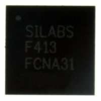
C8051F413-GM Silicon Laboratories Inc, C8051F413-GM Datasheet - Page 10

C8051F413-GM
Manufacturer Part Number
C8051F413-GM
Description
IC 8051 MCU 16K FLASH 28QFN
Manufacturer
Silicon Laboratories Inc
Series
C8051F41xr
Specifications of C8051F413-GM
Program Memory Type
FLASH
Program Memory Size
16KB (16K x 8)
Package / Case
28-QFN
Core Processor
8051
Core Size
8-Bit
Speed
50MHz
Connectivity
SMBus (2-Wire/I²C), SPI, UART/USART
Peripherals
Brown-out Detect/Reset, POR, PWM, Temp Sensor, WDT
Number Of I /o
20
Ram Size
2.25K x 8
Voltage - Supply (vcc/vdd)
2 V ~ 5.25 V
Data Converters
A/D 20x12b; D/A 2x12b
Oscillator Type
Internal
Operating Temperature
-40°C ~ 85°C
Processor Series
C8051F4x
Core
8051
Data Bus Width
8 bit
Data Ram Size
2.25 KB
Interface Type
I2C/SMBus/SPI/UART
Maximum Clock Frequency
50 MHz
Number Of Programmable I/os
20
Number Of Timers
4
Operating Supply Voltage
2 V to 5.25 V
Maximum Operating Temperature
+ 85 C
Mounting Style
SMD/SMT
3rd Party Development Tools
PK51, CA51, A51, ULINK2
Development Tools By Supplier
C8051F410DK
Minimum Operating Temperature
- 40 C
On-chip Dac
2-ch x 12-bit
Lead Free Status / RoHS Status
Lead free / RoHS Compliant
For Use With
770-1006 - ISP 4PORT FOR SILABS C8051F MCU336-1454 - ADAPTER PROGRAM TOOLSTICK F411336-1317 - KIT EVAL FOR C8051F411336-1314 - KIT DEV FOR C8051F41X
Eeprom Size
-
Lead Free Status / Rohs Status
Lead free / RoHS Compliant
Other names
336-1311
Available stocks
Company
Part Number
Manufacturer
Quantity
Price
Company:
Part Number:
C8051F413-GM
Manufacturer:
Silicon Labs
Quantity:
135
Part Number:
C8051F413-GM
Manufacturer:
SILICON LABS/芯科
Quantity:
20 000
Company:
Part Number:
C8051F413-GMR
Manufacturer:
M/A-COM
Quantity:
1 001
Part Number:
C8051F413-GMR
Manufacturer:
SILICON LABS/芯科
Quantity:
20 000
C8051F410/1/2/3
10. CIP-51 Microcontroller
11. Memory Organization and SFRs
12. Interrupt Handler
13. Prefetch Engine
14. Cyclic Redundancy Check Unit (CRC0)
15. Reset Sources
16. Flash Memory
17. External RAM
18. Port Input/Output
19. Oscillators
20. smaRTClock (Real Time Clock)
21. SMBus
22. UART0
10
Figure 9.3. Comparator Hysteresis Plot ................................................................... 85
Figure 10.1. CIP-51 Block Diagram.......................................................................... 93
Figure 11.1. Memory Map ...................................................................................... 103
Figure 14.1. CRC0 Block Diagram ......................................................................... 121
Figure 14.2. Bit Reverse Register .......................................................................... 124
Figure 15.1. Reset Sources.................................................................................... 127
Figure 15.2. Power-On and VDD Monitor Reset Timing ........................................ 128
Figure 16.1. Flash Program Memory Map.............................................................. 137
Figure 18.1. Port I/O Functional Block Diagram ..................................................... 147
Figure 18.2. Port I/O Cell Block Diagram ............................................................... 148
Figure 18.3. Crossbar Priority Decoder with No Pins Skipped ............................... 149
Figure 18.4. Crossbar Priority Decoder with Crystal Pins Skipped ........................ 150
Figure 18.5. Port 0 Input Overdrive Current Range................................................ 152
Figure 19.1. Oscillator Diagram.............................................................................. 165
Figure 19.2. 32.768 kHz External Crystal Example................................................ 169
Figure 19.3. Example Clock Multiplier Output ........................................................ 172
Figure 20.1. smaRTClock Block Diagram .............................................................. 177
Figure 21.1. SMBus Block Diagram ....................................................................... 191
Figure 21.2. Typical SMBus Configuration ............................................................. 192
Figure 21.3. SMBus Transaction ............................................................................ 193
Figure 21.4. Typical SMBus SCL Generation......................................................... 196
Figure 21.5. Typical Master Transmitter Sequence................................................ 202
Figure 21.6. Typical Master Receiver Sequence.................................................... 202
Figure 21.7. Typical Slave Receiver Sequence...................................................... 203
Figure 21.8. Typical Slave Transmitter Sequence.................................................. 204
Figure 22.1. UART0 Block Diagram ....................................................................... 207
Figure 22.2. UART0 Baud Rate Logic .................................................................... 208
Figure 22.3. UART Interconnect Diagram .............................................................. 209
Figure 22.4. 8-Bit UART Timing Diagram............................................................... 209
Figure 22.5. 9-Bit UART Timing Diagram............................................................... 210
Figure 22.6. UART Multi-Processor Mode Interconnect Diagram .......................... 211
Rev. 1.1


