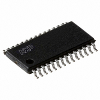
P89LPC931FDH,112 NXP Semiconductors, P89LPC931FDH,112 Datasheet - Page 29

P89LPC931FDH,112
Manufacturer Part Number
P89LPC931FDH,112
Description
IC 80C51 MCU FLASH 8K 28-TSSOP
Manufacturer
NXP Semiconductors
Series
LPC900r
Datasheet
1.P89LPC931FDH112.pdf
(55 pages)
Specifications of P89LPC931FDH,112
Core Processor
8051
Core Size
8-Bit
Speed
12MHz
Connectivity
I²C, SPI, UART/USART
Peripherals
Brown-out Detect/Reset, LED, POR, PWM, WDT
Number Of I /o
26
Program Memory Size
8KB (8K x 8)
Program Memory Type
FLASH
Ram Size
256 x 8
Voltage - Supply (vcc/vdd)
2.4 V ~ 3.6 V
Oscillator Type
Internal
Operating Temperature
-40°C ~ 85°C
Package / Case
28-TSSOP
Processor Series
P89LPC9x
Core
80C51
Data Bus Width
8 bit
Data Ram Size
256 B
Interface Type
I2C, SPI, UART
Maximum Clock Frequency
18 MHz
Number Of Programmable I/os
26
Number Of Timers
2
Operating Supply Voltage
2.4 V to 3.6 V
Maximum Operating Temperature
+ 85 C
Mounting Style
SMD/SMT
3rd Party Development Tools
PK51, CA51, A51, ULINK2
Minimum Operating Temperature
- 45 C
For Use With
622-1014 - BOARD FOR LPC9XX TSSOP622-1008 - BOARD FOR LPC9103 10-HVSON622-1006 - SOCKET ADAPTER BOARDMCB900K - BOARD PROTOTYPE NXP 89LPC9EPM900K - EMULATOR/PROGRAMMER NXP P89LPC9568-4000 - DEMO BOARD SPI/I2C TO DUAL UART568-3510 - DEMO BOARD SPI/I2C TO UART622-1002 - USB IN-CIRCUIT PROG LPC9XX568-1759 - EMULATOR DEBUGGER/PROGRMMR LPC9X568-1758 - BOARD EVAL FOR LPC93X MCU FAMILY
Lead Free Status / RoHS Status
Lead free / RoHS Compliant
Eeprom Size
-
Data Converters
-
Lead Free Status / Rohs Status
Details
Other names
568-1284-5
935273877112
P89LPC931FDH
P89LPC931FDH,129
P89LPC931FDH-S
935273877112
P89LPC931FDH
P89LPC931FDH,129
P89LPC931FDH-S
Philips Semiconductors
9397 750 14472
Product data
8.17.10 The 9
8.17.7 Break detect
8.17.8 Double buffering
8.17.9 Transmit interrupts with double buffering enabled (Modes 1, 2 and 3)
Break detect is reported in the status register (SSTAT). A break is detected when
11 consecutive bits are sensed LOW. The break detect can be used to reset the
device and force the device into ISP mode.
The UART has a transmit double buffer that allows buffering of the next character to
be written to SBUF while the first character is being transmitted. Double buffering
allows transmission of a string of characters with only one stop bit between any two
characters, as long as the next character is written between the start bit and the stop
bit of the previous character.
Double buffering can be disabled. If disabled (DBMOD, i.e., SSTAT.7 = ‘0’), the UART
is compatible with the conventional 80C51 UART. If enabled, the UART allows writing
to SnBUF while the previous data is being shifted out. Double buffering is only
allowed in Modes 1, 2 and 3. When operated in Mode 0, double buffering must be
disabled (DBMOD = ‘0’).
Unlike the conventional UART, in double buffering mode, the Tx interrupt is generated
when the double buffer is ready to receive new data.
If double buffering is disabled TB8 can be written before or after SBUF is written, as
long as TB8 is updated some time before that bit is shifted out. TB8 must not be
changed until the bit is shifted out, as indicated by the Tx interrupt.
If double buffering is enabled, TB8 must be updated before SBUF is written, as TB8
will be double-buffered together with SBUF data.
th
bit (bit 8) in double buffering (Modes 1, 2 and 3)
Rev. 05 — 15 December 2004
8-bit microcontrollers with two-clock 80C51 core
P89LPC930/931
© Koninklijke Philips Electronics N.V. 2004. All rights reserved.
29 of 55


