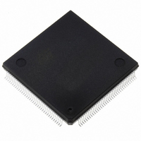
ST10F272Z2Q3 STMicroelectronics, ST10F272Z2Q3 Datasheet - Page 129

ST10F272Z2Q3
Manufacturer Part Number
ST10F272Z2Q3
Description
MCU 16BIT 256KB FLASH 144-PQFP
Manufacturer
STMicroelectronics
Series
ST10r
Datasheet
1.ST10F272Z2Q3.pdf
(189 pages)
Specifications of ST10F272Z2Q3
Core Processor
ST10
Core Size
16-Bit
Speed
64MHz
Connectivity
ASC, CAN, EBI/EMI, I²C, SSC, UART/USART
Peripherals
POR, PWM, WDT
Number Of I /o
111
Program Memory Size
256KB (256K x 8)
Program Memory Type
FLASH
Ram Size
20K x 8
Voltage - Supply (vcc/vdd)
4.5 V ~ 5.5 V
Data Converters
A/D 24x10b
Oscillator Type
Internal
Operating Temperature
-40°C ~ 125°C
Package / Case
144-QFP
Lead Free Status / RoHS Status
Lead free / RoHS Compliant
Eeprom Size
-
Other names
497-5579
Available stocks
Company
Part Number
Manufacturer
Quantity
Price
Company:
Part Number:
ST10F272Z2Q3
Manufacturer:
E-CMOS
Quantity:
10 000
Company:
Part Number:
ST10F272Z2Q3
Manufacturer:
STMicroelectronics
Quantity:
10 000
- Current page: 129 of 189
- Download datasheet (4Mb)
ST10F272Z2
24.1
Injected conversion stalling the ADC
Description
Whenever a new injection request occurs before the ADDAT2 register has been read by the
CPU (that is, when the result of the previous injection request has not been read), the ADC
is stalled and no further conversions are performed.
Workaround
The following actions make it possible to unlock the ADC module:
1.
2.
Application conditions
This problem can occur if all the following conditions are fulfilled:
●
●
●
Therefore, to prevent the locking situation from occurring, it is important to make sure that,
at application level, no task can disable interrupts for a period of time during which 2
injection requests can occur before a read operation is performed.
Detailed analysis
Channel injection mode allows the conversion of a specific analog channel without changing
the current operating mode. It can also be used while the ADC is running in a continuous or
auto scan mode.
The following main points need to be highlighted:
●
●
●
If the temporary data register used for ADDAT2 read mode is full and a new injection request
occurs then the new converted value is stored into a temporary data register until the
previous one is read from ADDAT2.
To ensure a correct operation as soon as ADDAT2 register is read, the last converted value
should be moved from temporary register to ADDAT2 and the ADEINT interrupt should be
requested.
In real circumstances, as soon as ADDAT2 register is read then the last converted value is
correctly moved from temporary register to ADDAT2 but the ADEINT interrupt request is not
received by the Interrupt Controller (see
Read the ADDAT2 register twice at the end of every injected conversion. This action
also prevents the ADC from being stalled).
Disable and then enable again the wait for read mode
Injection requests are hardware triggered (via CapCom CC31)
The result of injected conversions is read via a PEC transfer. This prevents from
reading twice the ADDAT2 register by software)
A high level task is disabling the PEC transfer for a long time (2 analog conversions +
time between 2 injection requests)
Wait for ADDAT read mode is needed in order for the ADC Channel Injection mode to
operate properly
At the end of the injected conversion the data is available in the alternate result register
ADDAT2 and a Channel Injection Complete Interrupt request is generated (ADEIR
Flag)
If the temporary data register used for ADDAT2 read mode is full, the next conversion
(standard or injected) is suspended. The temporary register then stores the content of
ADDAT (standard conversion) or ADDAT2 (from an injected conversion).
The last converted value can then be read by the CPU. See
Figure
38). As a consequence, the CPU/PEC can
Figure
Known limitations
37.
129/189
Related parts for ST10F272Z2Q3
Image
Part Number
Description
Manufacturer
Datasheet
Request
R

Part Number:
Description:
STMicroelectronics [RIPPLE-CARRY BINARY COUNTER/DIVIDERS]
Manufacturer:
STMicroelectronics
Datasheet:

Part Number:
Description:
STMicroelectronics [LIQUID-CRYSTAL DISPLAY DRIVERS]
Manufacturer:
STMicroelectronics
Datasheet:

Part Number:
Description:
BOARD EVAL FOR MEMS SENSORS
Manufacturer:
STMicroelectronics
Datasheet:

Part Number:
Description:
NPN TRANSISTOR POWER MODULE
Manufacturer:
STMicroelectronics
Datasheet:

Part Number:
Description:
TURBOSWITCH ULTRA-FAST HIGH VOLTAGE DIODE
Manufacturer:
STMicroelectronics
Datasheet:

Part Number:
Description:
Manufacturer:
STMicroelectronics
Datasheet:

Part Number:
Description:
DIODE / SCR MODULE
Manufacturer:
STMicroelectronics
Datasheet:

Part Number:
Description:
DIODE / SCR MODULE
Manufacturer:
STMicroelectronics
Datasheet:

Part Number:
Description:
Search -----> STE16N100
Manufacturer:
STMicroelectronics
Datasheet:

Part Number:
Description:
Search ---> STE53NA50
Manufacturer:
STMicroelectronics
Datasheet:

Part Number:
Description:
NPN Transistor Power Module
Manufacturer:
STMicroelectronics
Datasheet:


