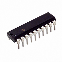
PIC16C770-I/P Microchip Technology, PIC16C770-I/P Datasheet - Page 122

PIC16C770-I/P
Manufacturer Part Number
PIC16C770-I/P
Description
IC MCU CMOS A/D 2K 20MHZ 20-DIP
Manufacturer
Microchip Technology
Series
PIC® 16Cr
Datasheets
1.PIC16C770-ISO.pdf
(220 pages)
2.PIC16C770-ISO.pdf
(6 pages)
3.PIC16C770-ISO.pdf
(8 pages)
Specifications of PIC16C770-I/P
Core Size
8-Bit
Program Memory Size
3.5KB (2K x 14)
Oscillator Type
Internal
Core Processor
PIC
Speed
20MHz
Connectivity
I²C, SPI
Peripherals
Brown-out Detect/Reset, POR, PWM, WDT
Number Of I /o
15
Program Memory Type
OTP
Ram Size
256 x 8
Voltage - Supply (vcc/vdd)
4 V ~ 5.5 V
Data Converters
A/D 6x12b
Operating Temperature
-40°C ~ 85°C
Package / Case
20-DIP (0.300", 7.62mm)
Controller Family/series
PIC16C
No. Of I/o's
16
Ram Memory Size
256Byte
Cpu Speed
20MHz
No. Of Timers
3
No. Of
RoHS Compliant
Core
PIC
Processor Series
PIC16C
Data Bus Width
8 bit
Maximum Clock Frequency
20 MHz
Data Ram Size
256 B
Data Rom Size
256 B
On-chip Adc
6 bit
Number Of Programmable I/os
16
Number Of Timers
3 bit
Operating Supply Voltage
2.5 V to 5.5 V
Mounting Style
Through Hole
Height
3.3 mm
Interface Type
I2C, SPI, SSP
Length
26.16 mm
Maximum Operating Temperature
+ 85 C
Minimum Operating Temperature
- 40 C
Supply Voltage (max)
5.5 V
Supply Voltage (min)
4 V
Width
6.35 mm
Lead Free Status / RoHS Status
Lead free / RoHS Compliant
For Use With
DVA16XP200 - ADAPTER ICE 20DIP/SOIC/SSOPAC164028 - MODULE SKT PROMATEII 20SOIC/DIP
Eeprom Size
-
Lead Free Status / Rohs Status
Details
Other names
PIC16C770I/P
PIC16C717/770/771
12.2.4
For timing insensitive applications, the ER (External
Resistor) Clock mode offers additional cost savings.
Only one external component, a resistor connected to
the OSC1 pin and V
frequency of the internal oscillator. The resistor draws
a DC bias current which controls the oscillation fre-
quency. In addition to the resistance value, the oscilla-
tor frequency will vary from unit to unit, and as a
function of supply voltage and temperature. Since the
controlling parameter is a DC current and not a capac-
itance, the particular package type and lead frame will
not have a significant effect on the resultant frequency.
Figure 12-3 shows how the controlling resistor is con-
nected to the PIC16C717/770/771. For R
below 38 k , the oscillator operation may become
unstable, or stop completely. For very high R
(e.g. 1M), the oscillator becomes sensitive to noise,
humidity and leakage. Thus, we recommend keeping
R
FIGURE 12-3:
The Electrical Specification section shows the relation-
ship between the R
ating frequency as well as frequency variations due to
operating temperature for given R
The ER Oscillator mode has two options that control
the OSC2 pin. The first allows it to be used as a general
purpose I/O port. The other configures the pin as CLK-
OUT. The ER oscillator does not run during RESET.
12.2.5
The internal RC oscillator provides a fixed 4 MHz (nom-
inal) system clock at V
cal Specifications” section for information on variation
over voltage and temperature. The INTRC oscillator
does not run during RESET.
DS41120B-page 120
EXT
between 38 k and 1 M .
R
EXT
ER MODE
INTRC MODE
EXT
SS
EXTERNAL RESISTOR
, is needed to set the operating
DD
resistance value and the oper-
= 5V and 25 C, see “Electri-
RA6/OSC2/CLKOUT
RA7/OSC1/CLKIN
PIC16C717/770/771
EXT
and V
EXT
EXT
DD
values.
values
values
12.2.6
In the INTRC and ER modes, the PIC16C717/770/771
can be configured to provide a clock out signal by pro-
gramming the configuration word. The oscillator fre-
quency, divided by 4, can be used for test purposes or
to synchronize other logic.
In the INTRC and ER modes, if the CLKOUT output is
enabled, CLKOUT is held low during RESET.
12.2.7
A software programmable dual speed oscillator is avail-
able in either ER or INTRC Oscillator modes. This fea-
ture allows the applications to dynamically toggle the
oscillator speed between normal and slow frequencies.
The nominal slow frequency is 37 kHz. In ER mode, the
slow speed operation is fixed and does not vary with
resistor size. Applications that require low current
power savings, but cannot tolerate putting the part into
SLEEP, may use this mode.
The OSCF bit in the PCON register is used to control
Dual
Register 2-8, for details.
When changing the INTRC or ER internal oscillator
speed, there is a period of time when the processor is
inactive. When the speed changes from fast to slow,
the processor inactive period is in the range of 100 S
to 300 S. For speed change from slow to fast, the pro-
cessor is in active for 1.25 S to 3.25 S.
Speed
CLKOUT
DUAL SPEED OPERATION FOR ER
AND INTRC MODES
mode.
See
2002 Microchip Technology Inc.
the PCON Register,


