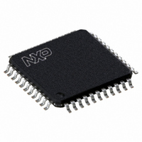
P89CV51RD2FBC,557 NXP Semiconductors, P89CV51RD2FBC,557 Datasheet - Page 35

P89CV51RD2FBC,557
Manufacturer Part Number
P89CV51RD2FBC,557
Description
IC 80C51 MCU FLASH 64K 44-TQFP
Manufacturer
NXP Semiconductors
Series
89Cr
Datasheet
1.P89CV51RB2FA512.pdf
(76 pages)
Specifications of P89CV51RD2FBC,557
Core Processor
8051
Core Size
8-Bit
Speed
40MHz
Connectivity
EBI/EMI, SPI, UART/USART
Peripherals
POR, PWM, WDT
Number Of I /o
32
Program Memory Size
64KB (64K x 8)
Program Memory Type
FLASH
Ram Size
1K x 8
Voltage - Supply (vcc/vdd)
4.5 V ~ 5.5 V
Oscillator Type
Internal
Operating Temperature
-40°C ~ 85°C
Package / Case
44-TQFP, 44-VQFP
Processor Series
P89CV5x
Core
80C51
Data Bus Width
8 bit
Data Ram Size
1 KB
Interface Type
SPI, UART
Maximum Clock Frequency
40 MHz
Number Of Programmable I/os
32
Number Of Timers
3
Operating Supply Voltage
4.5 V to 5.5 V
Maximum Operating Temperature
+ 85 C
Mounting Style
SMD/SMT
3rd Party Development Tools
PK51, CA51, A51, ULINK2
Minimum Operating Temperature
- 40 C
Cpu Family
89C
Device Core
80C51
Device Core Size
8b
Frequency (max)
40MHz
Total Internal Ram Size
1KB
# I/os (max)
32
Number Of Timers - General Purpose
3
Operating Supply Voltage (typ)
5V
Operating Supply Voltage (max)
5.5V
Operating Supply Voltage (min)
4.5V
Instruction Set Architecture
CISC
Operating Temp Range
-40C to 85C
Operating Temperature Classification
Industrial
Mounting
Surface Mount
Pin Count
44
Package Type
TQFP
Lead Free Status / RoHS Status
Lead free / RoHS Compliant
Eeprom Size
-
Data Converters
-
Lead Free Status / Rohs Status
Details
Other names
568-4257
935284103557
P89CV51RD2FBC
935284103557
P89CV51RD2FBC
Available stocks
Company
Part Number
Manufacturer
Quantity
Price
Company:
Part Number:
P89CV51RD2FBC,557
Manufacturer:
NXP Semiconductors
Quantity:
10 000
NXP Semiconductors
P89CV51RB2_RC2_RD2_3
Product data sheet
6.5.5 Summary of baud rate equations
The Baud rate generator mode is like the Auto-reload mode, when a roll-over in TH2
causes the Timer 2 registers to be reloaded with the 16-bit value in registers RCAP2H and
RCAP2L, which are preset by software.
The baud rates in modes 1 and 3 are determined by Timer 2’s overflow rate given below:
The timer can be configured for either ‘timer’ or ‘counter’ operation. In many applications,
it is configured for ‘timer' operation (C/T2 = 0). Timer operation is different for Timer 2
when it is being used as a baud rate generator.
Usually, as a timer it would increment at every machine cycle (i.e.,
frequency). As a baud rate generator, it increments at the oscillator frequency. Thus the
baud rate formula is shown in
Where: (RCAP2H, RCAP2L) = the content of RCAP2H and RCAP2L taken as a 16-bit
unsigned integer.
The Timer 2 in Baud rate generator mode is valid only if RCLK and/or TCLK = 1 in T2CON
register. Note that a roll-over in TH2 does not set TF2, and will not generate an interrupt.
Thus, the Timer 2 interrupt does not have to be disabled when Timer 2 is in the Baud rate
generator mode. Also if the EXEN2 (T2 external enable flag) is set, a 1-to-0 transition in
T2EX (timer/counter 2 trigger input) will set EXF2 (T2 external flag) but will not cause a
reload from (RCAP2H, RCAP2L) to (TH2, TL2). Therefore when Timer 2 is used as a
baud rate generator, T2EX can be used as an additional external interrupt, if needed.
When Timer 2 is in the Baud rate generator mode, one should not try to read or write TH2
and TL2. Under these conditions, a read or write of TH2 or TL2 may not be accurate. The
RCAP2 registers may be read, but should not be written to, because a write might overlap
a reload and cause write and/or reload errors. The timer should be turned off (clear TR2)
before accessing the Timer 2 or RCAP2 registers.
rates and how they can be obtained from Timer 2.
Timer 2 is in Baud rate generator mode: if Timer 2 is being clocked through pin T2 (P1[0])
the baud rate is:
If Timer 2 is being clocked internally, the baud rate is:
Where f
To obtain the reload value for RCAP2H and RCAP2L, this equation can be rewritten as:
---------------------------------------------------------------------------------------------
16
Modes 1 and 3 baud rates = Timer 2 overflow rate / 16
Modes 1 and 3 baud rates =
Baud rate = Timer 2 overflow rate / 16
Baud rate = f
RCAP2H, RCAP2L = 65536
65536
OscillatorFrequency
osc
= oscillator frequency
–
RCAP2H RCAP2L
osc
/ (16
Rev. 03 — 25 August 2009
(65536
Equation
f
osc
(RCAP2H, RCAP2L)))
/ (16
3:
P89CV51RB2/RC2/RD2
baud rate)
Table 23
shows commonly used baud
80C51 with 1 kB RAM, SPI
1
6
the oscillator
© NXP B.V. 2009. All rights reserved.
35 of 76
(3)


