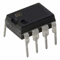
ST7FLITEUS5B6 STMicroelectronics, ST7FLITEUS5B6 Datasheet - Page 134

ST7FLITEUS5B6
Manufacturer Part Number
ST7FLITEUS5B6
Description
MCU 8BIT 1KB FLASH 128KB 8-DIP
Manufacturer
STMicroelectronics
Series
ST7r
Datasheet
1.STEVAL-IFS006V1.pdf
(136 pages)
Specifications of ST7FLITEUS5B6
Core Processor
ST7
Core Size
8-Bit
Speed
8MHz
Peripherals
LVD, POR, PWM, WDT
Number Of I /o
5
Program Memory Size
1KB (1K x 8)
Program Memory Type
FLASH
Ram Size
128 x 8
Voltage - Supply (vcc/vdd)
2.4 V ~ 5.5 V
Data Converters
A/D 5x10b
Oscillator Type
Internal
Operating Temperature
-40°C ~ 85°C
Package / Case
8-DIP (0.300", 7.62mm)
Controller Family/series
ST7
No. Of I/o's
5
Ram Memory Size
128Byte
Cpu Speed
8MHz
No. Of Timers
2
Rohs Compliant
Yes
For Use With
497-6403 - BOARD EVAL 8BIT MICRO + TDE1708497-6407 - BOARD EVAL FOR VACUUM CLEANER497-5861 - EVAL BRD POWER MOSFET/8PIN MCU497-5858 - EVAL BOARD PLAYBACK ST7FLITE497-5515 - EVAL BOARD PHASE CTRL DIMMER497-5049 - KIT STARTER RAISONANCE ST7FLITE497-5046 - KIT TOOL FOR ST7/UPSD/STR7 MCU
Lead Free Status / RoHS Status
Lead free / RoHS Compliant
Eeprom Size
-
Connectivity
-
Other names
497-5636-5
Available stocks
Company
Part Number
Manufacturer
Quantity
Price
Company:
Part Number:
ST7FLITEUS5B6
Manufacturer:
STMicroelectronics
Quantity:
8
Revision history
16
Table 82.
134/136
06-Feb-06
18-Apr-06
Date
Revision history
Document revision history
Revision
1
2
Initial release
Removed references to 3% RC
Added note below
Modified presentation of
Added notes to
10-bit calibration value and changed application note reference (AN2326
instead of AN1324)
Modifed
description of CKCNTCSR register
Modified Figure 13 (added CKCNTCSR register)
Added note 2 to EICRx description
Modified caution in
Replaced V
Modified LVDRF bit description in
Replaced “oscillator” by “main oscillator” in the second paragraph of
Section 8.4.2: Halt mode
Added note 1 to
Modified
Replaced bit 1 by bit 2 for AWUF bit in
Modified
function.Updated
conditions with low voltage detector
Modified
Table 49: Voltage drop between AVD flag set and LVD reset
Modified
Supply
General
Table 65: Asynchronous RESET pin
ADC
Added
Figure 62
ECOPACK text in
in
Table
Development
Section :
Section 14: Device configuration and ordering
characteristics.
79. Modified conditioning option in option list. Modified
Figure
current. Modified
Table 7: Clock register map and reset values
characteristics. Modified
Section 8.5: Auto-wakeup from Halt mode
Section 9.1:
Table 48: Auxiliary Voltage Detector (AVD)
Table 50: Internal RC oscillator calibrated at 5
. Added erratasheet at the end of the document.
(device works correctly without these components). Added
IT+(LVD)
tools. Added
49. Modified
Section 6.2
Figure 23
Section 9.5:
Section 13: Package
Figure 4
by V
section 7.2 on page 25
Introduction. Modified
IT+(LVD)
Section 4.3.1
Table 54: On-chip
and added note 5 to
Section 14.4: ST7 application
Figure
(above
Interrupts. Modified
in
Table 64: Output driving
Section : Monitoring the VDD main supply
Section 7.4.4: Register description
61. Removed EMC protection circuitry in
Changes
Figure
(LVD).
characteristics. Modified
Section 8.5.1: Register description
characteristics. Modified first paragraph
9), replaced 8-bit calibration value to
peripherals. Modified
Section : External interrupt
Figure 24
ST7LITEUS2, ST7LITEUS5
information. Modified
Section Table 47.: Operating
Thresholds. Modified
and added bit 1 in the
V. Modified
notes. Added
current. Modified
generation.
Section 14.3:
Section 12.10:
Table 63:
Table 53:


