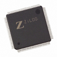
EZ80F93AZ020EC00TR Zilog, EZ80F93AZ020EC00TR Datasheet - Page 80

EZ80F93AZ020EC00TR
Manufacturer Part Number
EZ80F93AZ020EC00TR
Description
IC ACCLAIM MCU 64KB 100LQFP
Manufacturer
Zilog
Series
eZ80® Acclaim!®r
Specifications of EZ80F93AZ020EC00TR
Core Processor
Z8
Core Size
8-Bit
Speed
20MHz
Connectivity
I²C, IrDA, SPI, UART/USART
Peripherals
Brown-out Detect/Reset, POR, WDT
Number Of I /o
24
Program Memory Size
64KB (64K x 8)
Program Memory Type
FLASH
Ram Size
4K x 8
Voltage - Supply (vcc/vdd)
3 V ~ 3.6 V
Oscillator Type
Internal
Operating Temperature
-40°C ~ 105°C
Package / Case
100-LQFP
Lead Free Status / RoHS Status
Contains lead / RoHS non-compliant
Eeprom Size
-
Data Converters
-
Other names
EZ80F93AZ020EC00T
Available stocks
Company
Part Number
Manufacturer
Quantity
Price
- Current page: 80 of 261
- Download datasheet (4Mb)
PS015313-0508
Watchdog Timer Operation
Enabling and Disabling the WDT
The Watchdog Timer is disabled upon a RESET. To enable the WDT, the application
program must set the WDT_EN bit (bit 7) of the WDT_CTL register. When enabled, the
WDT cannot be disabled without a RESET.
Time-Out Period Selection
There are four choices of time-out periods for the WDT—2
clock cycles. The WDT time-out period is defined by the WDT_PERIOD field of the
WDT_CTL register (WDT_CTL[1:0]). The approximate time-out period for two
different WDT clock sources is listed in
Table 26. Watchdog Timer Approximate Time-Out Delays
RESET Or NMI Generation
On a WDT time-out, the RST_FLAG bit in the WDT_CTL register is set to 1. In addition,
the WDT can cause a RESET or send a nonmaskable interrupt (NMI) signal to the CPU.
The default operation is for the WDT to cause a RESET. It asserts/deasserts on the rising
edge of the clock. The RST_FLAG bit can be polled by the CPU to determine the source
of the RESET event.
Clock Source
32.768 kHz Crystal Oscillator
32.768 kHz Crystal Oscillator
32.768 kHz Crystal Oscillator
32.768 kHz Crystal Oscillator
20 MHz System Clock
20 MHz System Clock
20 MHz System Clock
20 MHz System Clock
50 MHz System Clock
50 MHz System Clock
50 MHz System Clock
50 MHz System Clock
Note: *WDT time-out values should be sufficiently long to allow Flash
operations to complete.
Divider Value
2
2
2
2
2
2
2
2
2
2
2
2
18
22
25
27
18
22
25
27
18
22
25
27
Table
26.
Time Out Delay
209.7 ms*
13.1 ms*
83.9 ms
4096 s
5.2 ms
1024 s
1.68 s
6.71 s
0.67 s
2.68 s
8.00 s
128 s
18
, 2
22
Product Specification
, 2
25
eZ80F92/eZ80F93
, and 2
Watchdog Timer
27
system
73
Related parts for EZ80F93AZ020EC00TR
Image
Part Number
Description
Manufacturer
Datasheet
Request
R

Part Number:
Description:
Communication Controllers, ZILOG INTELLIGENT PERIPHERAL CONTROLLER (ZIP)
Manufacturer:
Zilog, Inc.
Datasheet:

Part Number:
Description:
KIT DEV FOR Z8 ENCORE 16K TO 64K
Manufacturer:
Zilog
Datasheet:

Part Number:
Description:
KIT DEV Z8 ENCORE XP 28-PIN
Manufacturer:
Zilog
Datasheet:

Part Number:
Description:
DEV KIT FOR Z8 ENCORE 8K/4K
Manufacturer:
Zilog
Datasheet:

Part Number:
Description:
KIT DEV Z8 ENCORE XP 28-PIN
Manufacturer:
Zilog
Datasheet:

Part Number:
Description:
DEV KIT FOR Z8 ENCORE 4K TO 8K
Manufacturer:
Zilog
Datasheet:

Part Number:
Description:
CMOS Z8 microcontroller. ROM 16 Kbytes, RAM 256 bytes, speed 16 MHz, 32 lines I/O, 3.0V to 5.5V
Manufacturer:
Zilog, Inc.
Datasheet:

Part Number:
Description:
Low-cost microcontroller. 512 bytes ROM, 61 bytes RAM, 8 MHz
Manufacturer:
Zilog, Inc.
Datasheet:

Part Number:
Description:
Z8 4K OTP Microcontroller
Manufacturer:
Zilog, Inc.
Datasheet:

Part Number:
Description:
CMOS SUPER8 ROMLESS MCU
Manufacturer:
Zilog, Inc.
Datasheet:

Part Number:
Description:
SL1866 CMOSZ8 OTP Microcontroller
Manufacturer:
Zilog, Inc.
Datasheet:

Part Number:
Description:
SL1866 CMOSZ8 OTP Microcontroller
Manufacturer:
Zilog, Inc.
Datasheet:

Part Number:
Description:
OTP (KB) = 1, RAM = 125, Speed = 12, I/O = 14, 8-bit Timers = 2, Comm Interfaces Other Features = Por, LV Protect, Voltage = 4.5-5.5V
Manufacturer:
Zilog, Inc.
Datasheet:

Part Number:
Description:
Manufacturer:
Zilog, Inc.
Datasheet:


