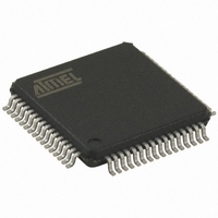
AT89C5122D-RDRIM Atmel, AT89C5122D-RDRIM Datasheet - Page 73

AT89C5122D-RDRIM
Manufacturer Part Number
AT89C5122D-RDRIM
Description
IC MCU 80C51 W/SMART CARD 64VQFP
Manufacturer
Atmel
Series
89Cr
Specifications of AT89C5122D-RDRIM
Core Processor
8051
Core Size
8-Bit
Speed
48MHz
Connectivity
SmartCard, SPI, UART/USART, USB
Peripherals
LED, POR, WDT
Number Of I /o
46
Program Memory Size
32KB (32K x 8)
Program Memory Type
FLASH
Ram Size
768 x 8
Voltage - Supply (vcc/vdd)
3 V ~ 5.5 V
Oscillator Type
Internal
Operating Temperature
-40°C ~ 85°C
Package / Case
64-TQFP, 64-VQFP
For Use With
AT89STK-10 - KIT EVAL APPL MASS STORAGEAT89STK-03 - KIT STARTER FOR MCU AT8XC5122/23
Lead Free Status / RoHS Status
Contains lead / RoHS non-compliant
Eeprom Size
-
Data Converters
-
Other names
AT89C5122DRDRIMTR
Available stocks
Company
Part Number
Manufacturer
Quantity
Price
- Current page: 73 of 208
- Download datasheet (3Mb)
Transmit / Receive Buffer
4202F–SCR–07/2008
The contents of the SCIBUF Transmit / Receive Buffer is transferred or received into /
from the Shift Register. The Shift Register is not accessible by microcontroller. Its role is
to prepare the byte to be copied on the I/O pin for a transmission or in the SCIBUF
buffer after a reception.
During a character transmission process, as soon as the contents of the SCIBUF buffer
is transferred to the shift register, the SCTBE bit is set in SCISR register to indicate that
the SCIBUF buffer is empty and ready to accept a new byte. This mechanism avoids to
wait for the complete transmission of the previous byte before writing a new byte in the
buffer and enables to speed up the transmission.
During a character reception process, the contents of the Shift Register is transferred in
the SCIBUF buffer.
Warning : the SCTBI, SCTI SCRI and SCPI bits have the same function as SCTBE,
SCTC, SCRC and SCPE bits. The first ones are able to generate interruptions if the
interruptions are enabled in SCIER register while the second ones are only status bits to
be used in pulling mode. If the interruption mode is not used, the status bits must be
used. The SCTBI, SCTI and SCRI bits do not contain valid information while their
respective interrupt enable bits ESCTBI, EXCTI, ESCRI are cleared.
–
–
–
–
If the Character repetition mode is not selected (bit CREP=0 in SCICR), as
soon as the contents of the Shift Register is transferred to I/O pin, the SCTC
bit is set in SCISR register to indicate that the byte has been transmitted.
If the Character repetition mode is selected (bit CREP=1 in SCICR) The
TERMINAL will be able to repeat characters as requested by the ICC (See
the Parity Error in T=0 protocol description in the definition paragraph
above). The SCTC bit in SCISR register will be set after a successful
transmission (no retry or no further retry requested by the ICC). If the
number of retries is exhausted (up to 4 retries depending on CREPSEL bit in
SCSR) and the last retry is still unsuccessful, the SCTC bit in SCISR will not
be set and the SCPE bit in SCISR register will be set instead.
If the Character repetition mode is not selected (bit CREP=0 in SCICR), as
soon as the contents of the Shift Register is transferred to the SCIBUF the
SCRC bit is set in SCISR register to indicate that the byte has been
received, and the SCIBUF contains a valid character ready to be red by the
microcontroller.
If the Character repetition mode is selected (bit CREP=1 in SCICR) The
TERMINAL will be able to request repetition if the received character exhibit
a parity error. Up to 4 retries can be requested depending on CREPSEL bit
in SCSR. The SCRC bit will be set in SCISR register after a successful
reception, first reception or after retry(ies). If the number of retries is
exhausted (up to 4 retries depending on CREPSEL bit in SCSR) and the last
retry is still unsuccessful, the SCRC bit and the SCPE bit in SCISR register
will be set. It will be possible to read the erroneous character.
AT83R5122, AT8xC5122/23
73
Related parts for AT89C5122D-RDRIM
Image
Part Number
Description
Manufacturer
Datasheet
Request
R

Part Number:
Description:
IC 8051 MCU 32K CRAM USB 64-VQFP
Manufacturer:
Atmel
Datasheet:

Part Number:
Description:
IC 8051 MCU W/SMART CARD 64VQFP
Manufacturer:
Atmel
Datasheet:

Part Number:
Description:
IC 8051 MCU FLASH 32K 64QFN
Manufacturer:
Atmel
Datasheet:

Part Number:
Description:
IC 8051 MCU FLASH 32K 64VQFP
Manufacturer:
Atmel
Datasheet:

Part Number:
Description:
IC 8051 MCU FLASH 32K 28PLCC
Manufacturer:
Atmel
Datasheet:

Part Number:
Description:
MICROCONTROLLER WITH USB AND SMART CARD READER INTERFACES
Manufacturer:
ATMEL [ATMEL Corporation]
Datasheet:

Part Number:
Description:
KIT STARTER FOR MCU AT8XC5122/23
Manufacturer:
Atmel
Datasheet:

Part Number:
Description:
IC MICRO CTRL 24MHZ 44TQFP
Manufacturer:
Atmel
Datasheet:

Part Number:
Description:
IC MICRO CTRL 24MHZ 44PLCC
Manufacturer:
Atmel
Datasheet:

Part Number:
Description:
IC MICRO CTRL 24MHZ 44PLCC
Manufacturer:
Atmel
Datasheet:

Part Number:
Description:
IC MICRO CTRL 24MHZ 40DIP
Manufacturer:
Atmel
Datasheet:


