HD64F3694FY Renesas Electronics America, HD64F3694FY Datasheet - Page 15
HD64F3694FY
Manufacturer Part Number
HD64F3694FY
Description
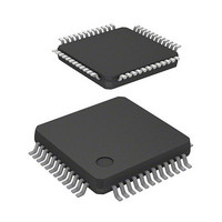
IC H8 MCU FLASH 32K 48-LQFP
Manufacturer
Renesas Electronics America
Series
H8® H8/300H Tinyr
Datasheet
1.HD64F3694GFYV.pdf
(452 pages)
Specifications of HD64F3694FY
Core Processor
H8/300H
Core Size
16-Bit
Speed
20MHz
Connectivity
I²C, SCI
Peripherals
PWM, WDT
Number Of I /o
29
Program Memory Size
32KB (32K x 8)
Program Memory Type
FLASH
Ram Size
2K x 8
Voltage - Supply (vcc/vdd)
3 V ~ 5.5 V
Data Converters
A/D 8x10b
Oscillator Type
Internal
Operating Temperature
-20°C ~ 75°C
Package / Case
48-LQFP
Lead Free Status / RoHS Status
Contains lead / RoHS non-compliant
Eeprom Size
-
Available stocks
Company
Part Number
Manufacturer
Quantity
Price

Part Number:
HD64F3694FYJV
Manufacturer:
RENESAS/瑞萨
Quantity:
20 000
Company:
Part Number:
HD64F3694FYV
Manufacturer:
Renesas Electronics America
Quantity:
10 000


11.4 Operation ........................................................................................................................... 144
11.5 Timer V Application Examples ......................................................................................... 148
11.6 Usage Notes ....................................................................................................................... 150
Section 12 Timer W ...........................................................................................153
12.1 Features.............................................................................................................................. 153
12.2 Input/Output Pins ............................................................................................................... 156
12.3 Register Descriptions ......................................................................................................... 156
12.4 Operation ........................................................................................................................... 165
12.5 Operation Timing............................................................................................................... 174
12.6 Usage Notes ....................................................................................................................... 179
Section 13 Watchdog Timer ..............................................................................183
13.1 Features.............................................................................................................................. 183
13.2 Register Descriptions ......................................................................................................... 184
11.3.2 Time Constant Registers A and B (TCORA, TCORB) ........................................ 139
11.3.3 Timer Control Register V0 (TCRV0) ................................................................... 140
11.3.4 Timer Control/Status Register V (TCSRV) .......................................................... 142
11.3.5 Timer Control Register V1 (TCRV1) ................................................................... 143
11.4.1 Timer V Operation................................................................................................ 144
11.5.1 Pulse Output with Arbitrary Duty Cycle............................................................... 148
11.5.2 Pulse Output with Arbitrary Pulse Width and Delay from TRGV Input .............. 149
12.3.1 Timer Mode Register W (TMRW) ....................................................................... 157
12.3.2 Timer Control Register W (TCRW) ..................................................................... 158
12.3.3 Timer Interrupt Enable Register W (TIERW) ...................................................... 159
12.3.4 Timer Status Register W (TSRW) ........................................................................ 160
12.3.5 Timer I/O Control Register 0 (TIOR0) ................................................................. 161
12.3.6 Timer I/O Control Register 1 (TIOR1) ................................................................. 163
12.3.7 Timer Counter (TCNT)......................................................................................... 164
12.3.8 General Registers A to D (GRA to GRD)............................................................. 164
12.4.1 Normal Operation ................................................................................................. 165
12.4.2 PWM Operation.................................................................................................... 169
12.5.1 TCNT Count Timing ............................................................................................ 174
12.5.2 Output Compare Output Timing ........................................................................... 174
12.5.3 Input Capture Timing............................................................................................ 175
12.5.4 Timing of Counter Clearing by Compare Match .................................................. 176
12.5.5 Buffer Operation Timing ...................................................................................... 176
12.5.6 Timing of IMFA to IMFD Flag Setting at Compare Match.................................. 177
12.5.7 Timing of IMFA to IMFD Setting at Input Capture ............................................. 178
12.5.8 Timing of Status Flag Clearing............................................................................. 178
Rev.5.00 Nov. 02, 2005 Page xiii of xxviii
Related parts for HD64F3694FY
Image
Part Number
Description
Manufacturer
Datasheet
Request
R

Part Number:
Description:
(HD64 Series) Hitachi Single-Chip Microcomputer
Manufacturer:
Hitachi Semiconductor
Datasheet:

Part Number:
Description:
KIT STARTER FOR M16C/29
Manufacturer:
Renesas Electronics America
Datasheet:

Part Number:
Description:
KIT STARTER FOR R8C/2D
Manufacturer:
Renesas Electronics America
Datasheet:

Part Number:
Description:
R0K33062P STARTER KIT
Manufacturer:
Renesas Electronics America
Datasheet:

Part Number:
Description:
KIT STARTER FOR R8C/23 E8A
Manufacturer:
Renesas Electronics America
Datasheet:

Part Number:
Description:
KIT STARTER FOR R8C/25
Manufacturer:
Renesas Electronics America
Datasheet:

Part Number:
Description:
KIT STARTER H8S2456 SHARPE DSPLY
Manufacturer:
Renesas Electronics America
Datasheet:

Part Number:
Description:
KIT STARTER FOR R8C38C
Manufacturer:
Renesas Electronics America
Datasheet:

Part Number:
Description:
KIT STARTER FOR R8C35C
Manufacturer:
Renesas Electronics America
Datasheet:

Part Number:
Description:
KIT STARTER FOR R8CL3AC+LCD APPS
Manufacturer:
Renesas Electronics America
Datasheet:
Part Number:
Description:
KIT STARTER FOR RX610
Manufacturer:
Renesas Electronics America
Datasheet:

Part Number:
Description:
KIT STARTER FOR R32C/118
Manufacturer:
Renesas Electronics America
Datasheet:

Part Number:
Description:
KIT DEV RSK-R8C/26-29
Manufacturer:
Renesas Electronics America
Datasheet:

Part Number:
Description:
KIT STARTER FOR SH7124
Manufacturer:
Renesas Electronics America
Datasheet:

Part Number:
Description:
KIT STARTER FOR H8SX/1622
Manufacturer:
Renesas Electronics America
Datasheet: